 Table of Contents
  Previous Chapter 8 Validating a System
This chapters provides general information related to validation in SDT and describes the actions you perform when validating an SDL system.
For a reference to the validator user interface, see chapter 33, The Validator.
The SDT Validator is a tool intended to support engineers involved in development of specifications or designs using SDL. It is designed to give the engineers a possibility to increase the quality of their work and to automate time-consuming tasks. It is focused on three major application areas in the development process:
Previous Chapter 8 Validating a System
This chapters provides general information related to validation in SDT and describes the actions you perform when validating an SDL system.
For a reference to the validator user interface, see chapter 33, The Validator.
The SDT Validator is a tool intended to support engineers involved in development of specifications or designs using SDL. It is designed to give the engineers a possibility to increase the quality of their work and to automate time-consuming tasks. It is focused on three major application areas in the development process:
- It provides an automated fault detection mechanism that finds inconsistencies and problems in an early stage of development. This is often referred to as validating an SDL system. See "Validating an SDL System" on page 401.
- When verifying the system against requirements, the Validator provides a possibility to perform automatic verification of the requirements expressed using the MSC (Message Sequence Chart) notation. See "Verifying an MSC" on page 411.
- When designing safety-critical or complex systems the Validator provides a possibility to test specific properties of the design. See "Using Observer Processes" on page 415.
An executable validator is built up in the same way as a simulator. See "Structure of a Simulator" on page 327 for more information.
The same interactive monitor system as for a simulator is used, but the set of available commands differ. The graphical user interface to the validator monitor, the Validator UI, works in the same way as the Simulator UI, but the set of available command buttons differ. For a description of some other differences, see "The Validator User Interface" on page 384.
The SDT Validator is based on a technique called state space exploration, which is a well-known technique for automatic analysis of distributed systems. All state space exploration tools for SDL are based on the idea of an automatic generation of the reachable state space for the SDL systems.
For readers interested in a more detailed description of the possibilities given by state space exploration for validation of distributed systems (focused on protocols), an excellent description is given in [1], see "References" on page 442.
The SDT Validator operates on structures known as behavior trees or reachability graphs. A behavior tree is a tree structure that represents the behavior of an SDL system.
The nodes of the tree represent SDL system states. A system state is defined by:
- The process instances that are active
- The variable values of these processes
- The SDL control flow state of the process instances
- Any procedure calls (with local variables etc.)
- Signals (with parameters) that are present in the queues of the system
- Active timers
- Etc.
The edges between the nodes in the tree represent atomic SDL events that transfers the SDL system from one system state to another. Therefore, the edges are also called behavior tree transitions. They can be individual SDL statements like tasks, inputs, outputs, etc. but also complete SDL transitions, depending on how the Validator is configured.
The size and structure of the behavior tree can thus vary and is determined by a number of Validator options. These options affect the number of system states generated for an SDL transition, and the number of possible behavior tree transitions from a state in the tree.
The set of all system states represented by the behavior tree is called the state space of the system. By moving around in the behavior tree, the behavior of the SDL system can be explored and the system states reached can be examined. This is known as state space exploration, and it can be performed both manually and automatically.
------------------------------------------------------------------------
Note:
The "children" of a node in the behavior tree are not generated until
a state space exploration actually reaches that node, i.e., the tree is
not a static structure generated when a validator is started.
------------------------------------------------------------------------
For each system state reached during state space exploration, a number of rules are checked to detect errors or possible problems in the SDL system. If a rule is violated, a report is generated to the user. By investigating the report and the system state where it was generated, the cause of the error can be determined.
The original start state of the system is called the system start state. It is the system state where the static process instances have been crated but their initial start transitions have not been executed.
The current state is the system state that currently is under investigation. It is changed when manually navigating in the behavior tree, or when going to the system state where a report has been generated. Initially, it is set to the system start state.
The current root of the behavior tree can be any system state. A number of Validator commands and features use it as a starting point of operation. Initially, it is set up to the system start state, also known as the original root of the behavior tree. If it is redefined, it is not possible to reach a state above the current root in the behavior tree without resetting it back to the original root.
A path between two states in the behavior tree can be denoted by a sequence of integers, each one indicating which transition was used to get between two states in the path. The current path is a path that is set up when manually navigating in the behavior tree, or when going to the system state where a report has been generated. When set up, it is the path between the current root and the current state. The current path is changed when the Validator moves to a state that is not part of the current path, e.g. when manually navigating to a system state outside of the current path. However, moving up and down along the current path does not change it.
There are two ways to generate and start a validator:
- A quick way in one single step, adequate for most situations
- A more complex way in several steps, giving you complete control of the generation and start process.
In the following, the more complex way will be described first, to give a full understanding of the process. The quick way is described in "Quick Start of a Validator" on page 383.
The Validator is implemented as a precompiled run-time kernel to the SDT C Code Generator in the same way the SDT Simulator is implemented. To start a Validator for an SDL system it is thus necessary to first generate an executable validator for the system. This is done from the SDT Organizer.
To generate an executable validator:
- Select Make from the Organizer's Generate menu. The Make dialog is opened.
- Turn on the options Analyze & generate code and Compile & link.
- From the Standard kernel option menu, select Validation.
- If you need to check the Analyzer options, click the Analyze Options button. In the dialog, set the options and click the Set button. For more information about these options, see "Analyzing using Customized Options" on page 312.
- Click the Make button.
A validator for the system is now generated in the current directory with the name <system>_xxx.val (the _xxx suffix is platform specific). The Status Bar of the Organizer reports the progress of the generation; the last message should be "Compiler done."
- Open the Organizer Log window from the Tools menu and check that no errors occurred and that a validator was generated.
An executable validator can be run in two different modes; graphical mode and stand-alone mode (textual mode).
In graphical mode, the Validator takes advantage of SDT's graphical user interface and integration mechanism. A separate graphical user interface, the Validator UI, is started, giving access to the monitor system through the use of menus, command buttons, etc.
To start a validator in graphical mode:
- Select Validator UI from the Organizer's Tools menu. The graphical user interface of the Validator is opened (see "The Graphical Interface" on page 385).
- Select Open from the Validator UI's File menu. A Standard File Selection Dialog dialog is opened.
- Alternatively, click the Open quick button in the tool bar.

- In the dialog, locate and select an executable validator and click OK.
A welcome message is printed in the text area of the Validator UI. The monitor system is now ready to accept commands.
In stand-alone mode, the Validator uses the input and output devices currently defined on your computer, which provide a textual, command-line based user interface. A very limited graphical support is provided when running the Validator in this mode.
To start a validator in stand-alone mode, the generated validator is executed directly from the OS prompt, e.g.
csh% ./system_vla.val
A welcome message is printed on the terminal:
Welcome to SDT VALIDATOR
Command :
The monitor system is now ready to accept commands.
--------------------------------------------------------------------
Note:
Before a validator can be run in stand-alone mode, you must execute
a command file from the operating system prompt. The file is called
telelogic.sou or telelogic.profile and is located in the
SDT binary directory that is included in your $path variable.


For csh-compatible shells: source <bin dir>/telelogic.sou


For sh-compatible shells: . <bin dir>/telelogic.profile
--------------------------------------------------------------------
A validator can also be generated and automatically started in graphical mode in one single step.
To quick start a validator, click the Validate quick button in the Organizer's tool bar. The following things happen:

- A validator is generated by using the validator kernel that is specified in the Make dialog. (If no validator kernel is specified, a default validator kernel is used.)
- The graphical Validator UI is started.
- The generated validator is started from the Validator UI.
An executing validator can be restarted from the beginning to reset its state completely:
- In graphical mode, select Restart from the Validator UI's File menu. (This is the same as opening the same validator again.) A confirmation dialog is opened.
- In stand-alone mode, the validator has to be exited with the Exit command and then executed from the OS prompt again.
When a validator is started, the static process instances in the system are created, but their initial transitions are not executed.
In some cases when the Validator is started, a message is printed that it is not possible to generate test values for all sorts and/or signal parameters. This has to do with the automatic test value generation mechanism that is used in the Validator. It happens if there are signals coming from the environment of the SDL system that have parameters of a sort that the test value generation cannot handle. To overcome this, define some test values for the sort that the Validator is complaining about. See "Defining Signals from the Environment" on page 421 for more information.
Monitor commands in the Validator are issued in the same way as in the Simulator, since the same monitor system is used in both tools. Also, the Validator UI works in the same way as the Simulator UI. Please see "Issuing Monitor Commands" on page 333 for more information.
The Validator UI can be customized in the same way as the Simulator UI. Please see "Customizing the Simulator UI" on page 337 for more information.
However, there are a few differences between the user interface of the Validator and the Simulator. These differences are described below.
The validator's monitor system becomes active when the validator is started, when a transition executed during navigation has completed, when an automatic state space exploration has finished, when a report with Abort action has been generated, or when an automatic state space exploration is manually stopped.
These conditions are listed in greater detail in "Activating the Monitor" on page 1888 in chapter 33, The Validator.
The graphical Validator UI is illustrated in the figure below:
Figure 180 : The Validator UI.
-----
(fig)

-----
Since the set of available commands differ between the Simulator UI and the Validator UI, the set of button modules and command buttons is also different. In addition, three extra menus are available in the menu bar: Commands Menu, Options1 Menu and Options2 Menu. The menu choices in these menus are similar to the command buttons in the sense that each of them correspond to a certain monitor command.
The Command and Watch windows are also available in the Validator UI. The differences compared to the Simulator UI are:
- In the Command window, the default commands that are executed are "List-Process -" and "Print-Trace 1".
- In the Watch window, a variable specification consists of the process instance name without parenthesis, followed by the variable name, e.g. game:1 count.
The SDT Validator provides the possibility to interactively walk around in the behavior tree of an SDL system. This is also known as manually navigating in the state space. A dedicated graphical tool, the Navigator, is available in the Validator to facilitate manual navigating. However, it is possible to use manual navigation without using the Navigator tool.
The Navigator is intended to be used in three different situations:
- When learning how a state space exploration tool like the Validator works, the Navigator is a convenient tool for interactively investigating the behavior tree of an SDL system.
- When using automatic state space exploration, there is sometimes a need to start the exploration from a different starting point than the system start state of the SDL system. In this case, the Navigator can be used to walk to a suitable system state, from which the automatic exploration can be started.
- When investigating a report generated during automatic exploration, the Navigator can be used to check the alternative behaviors that are possible on the path to the reported situation.
To open the Navigator tool, use one of the following methods:
The boxes shown in the Navigator represent the behavior tree transitions leading to and from the current system state. They are labelled
Up 1 (for the transition leading to the current state) and Next 1, Next 2, etc. (for the transitions leading from the current state).
To close the Navigator, click the Close quick button in the tool bar.

To move one level up in the behavior tree, use one of the following methods:
- In the Navigator, double-click the Up node, or select Up 1 from the pop-up menu available on the Up node.
- In the button module Explore, click the Up button.
- Enter the command Up 1.
To move more than one level up in the behavior tree at once:
- Enter the command Up, followed by the number of levels to move up.
To move to the current root of the behavior tree, i.e. the top of the current path, use one of the following methods:
- In the Navigator, select Up to top from the pop-up menu available on the Up node.
- In the button module Explore, click the Top button.
- Enter the command Top.
To see the possible Next nodes when the Navigator is not opened, enter the command List-Next. This gives a numbered list of all transitions leading from the current state.
To move one level down in the behavior tree, use one of the following methods:
- In the Navigator, double-click one of the Next nodes, or select Goto from the pop-up menu available on the Next nodes.
- Enter the command Next, followed by the number of the Next node, i.e. the number of the transition to execute.
To move more than one level down in the behavior tree at once:
- Enter the command Random-Down, followed by the number of levels to move down. For each level, a transition is chosen at random.
The current path can be seen as the path in the behavior tree that has been explored last. It is set up when going to a report (see "Going to a Report" on page 400) and when interactively walking down the behavior tree.
The transitions making up the current path are labelled with three asterisks "***" in the nodes in the Navigator. However, no such marking is present when the transitions are listed with the List-Next command.
To move up along the current path, use the Up or Top commands as described in "Moving Up in the Behavior Tree" above.
To move one level down along the current path, use one of the following methods:
- In the Navigator, double-click the Next node labelled with three asterisks "***", or select Goto from the pop-up menu available on this node.
- In the button module Explore, click the Down button.
- Enter the command Down 1.
To move more than one level down along the current path at once, enter the command Down, followed by the number of levels to move down.
To move to the bottom of the current path, use one of the following methods:
- In the button module Explore, click the Bottom button.
- Enter the command Bottom.
The current root of the behavior tree is initially set up to the system start state. The current root is automatically redefined to the current state when using MSC verification (see "Verifying an MSC" on page 411). It can also be redefined as an effect of changing validator options (see "Affecting the State Space" on page 430).
In addition, you can at any time redefine the current root to either the current state or back to the system start state. To do this, enter the command Define-Root. Select or enter Current to redefine the current root to the current state. Select or enter Original to redefine the current root to the system start state.
When using the Validator it is quite common that there is a need to go to a specific system state, for instance to be able to start an automatic state space exploration from this point. This section describe some possibilities to in an efficient way get to the wanted system state, called the target state below.
In many cases the simplest way is to use the Navigator tool or the navigation commands to interactively traverse the path to the target state. Manual navigation is described in "Navigating in the State Space" on page 386.
It is possible to return to a state that has been reached in an earlier stage when using the Validator. Three methods will be discussed:
The benefit of the first two techniques is that the exact same target state will be reached. The drawback is that these techniques will not work as soon as either the SDL system or the state space options have been changed (see "State Space Options" on page 436).
The benefit of the MSC technique is that it is less vulnerable to changes in the state space options or in the SDL system. The drawback is that the exact same target state may not be reached. We only know that the path to the reached system state will satisfy the generated MSC trace.
To go to the target state using path commands:
- When in the target state, enter the command Print-Path. The path from the root state to the current state is printed. The path is a sequence of integers indicating which transitions must be chosen to get to the current state.
- At a later stage, enter the command Goto-Path, followed by the path printed above.
To go to the target state using the command log:
- Before navigating to the target state, select Start Command Log from the Log menu, or enter the command Command-Log-On. Specify a file name on which all subsequent monitor commands will be stored.
- Navigate to the target state.
- Select Stop Command Log from the Log menu, or enter the command Command-Log-Off. The command logging is stopped and the file is closed.
- Return to the same state in which the command log was started.
- Execute the commands stored in the file by selecting Include Command Script from the Commands menu, or enter the command
Include-File. Select or specify the earlier file name.
To go to the target state using MSC trace:
- When in the target state, generate an MSC trace from the root state to the current state. Enter the command MSC-Log-File, followed by a file name.
- Return to the root state by using the Top command.
- Go to the end of the MSC trace by verifying the MSC. See "Verifying an MSC" on page 411.
If an MSC is created that describes the events leading to the target state, verifying this MSC gives a possibility to go to a system state that satisfies the MSC in an efficient way. It does not matter if the MSC is manually created, generated from the Simulator or from the Validator itself (as discussed in "Using MSC Trace" above). However, the exact same target state may not be reached by this method. We only know that the path to the reached system state will satisfy the generated MSC trace.
If the target state can be described in terms of process states, variable values, etc., a convenient way to get to a state that satisfies the description is to use a user-defined rule (see "Using User-Defined Rules" on page 426).
To go to a target state using a user-defined rule:
- Define the rule describing the target state (see "Managing User-Defined Rules" on page 427).
- Define the report action for user-defined rules reports to be Abort (see "Report Action" on page 434). This will cause an automatic exploration to stop as soon as a state is reached that satisfies the rule.
- Start an automatic state space exploration (see "Using a Default Exploration" on page 401).
- Go to the state where the rule was satisfied and a report was generated (see "Going to a Report" on page 400).
The benefit with this method is that it is fast and efficient, especially if the target state is on a considerable depth in the state space. The drawback is that sometimes there are shorter paths to the target state than the one that was automatically generated.
In the Validator, the same kind of commands as in the Simulator are available for tracing the execution, logging the user interaction and examining the system. There are a few differences, described below.
In the Validator, the same type of printed trace information is available for executed transitions as in the Simulator; see "Textual Trace" on page 344. Unlike the Simulator, however, there is no command to start continuously printing the textual trace; instead, a command must be explicitly used whenever a trace is wanted.
- To print a textual trace for the transitions leading to the current state, enter the command Print-Trace, followed by the number of transitions to trace. That is, Print-Trace 1 prints the trace for the latest transition. The same information as for a full trace during simulation is printed.
- By default, the command Print-Trace 1 is executed in the Command window of the Validator UI, i.e., a continuous trace is in practice available in graphical mode.
Graphical trace of SDL symbols in the source GR diagrams is available. The graphical trace in the Validator selects all symbols that were executed in the transition leading to the current state. This is different from the Simulator, where GR trace selects the next symbol to be executed.
- To enable or disable continuous graphical trace, enter the command SDL-Trace. This command toggles the graphical trace; the current state of the trace is printed after the command is executed. When the trace first is enabled, an SDL Editor is opened as soon as the next transition is executed.
- In the Validator UI, the graphical trace can be controlled from the Commands menu. The command Toggle SDL Trace toggles the trace between enabled and disabled.
MSC trace enables tracing of executed events in an MSC Editor. When the trace first is enabled, an MSC Editor is opened, showing the events executed up until the current state, and the current path is set up. After that, the trace is continuously updated in the Editor as transitions are executed. This means that events are added when you navigate down the behavior tree, the selected event is changed when you navigate up, and the MSC is redrawn when you move outside the current path.
- To enable or disable continuous MSC trace, enter the command MSC-Trace. This command toggles the trace; the current state of the trace is printed after the command is executed.
- In the Validator UI, the MSC trace can be controlled from the Commands menu. The command Toggle MSC Trace toggles the trace between enabled and disabled.
The MSC trace from the current root to the current state can also be saved on a log file, which later may be opened from an MSC Editor. To save such an MSC log, enter the command MSC-Log-File, followed by the file name. The MSC log file should be given the file extension .mpr.
Before an MSC trace is started, you may define what types of events that will be traced. See "MSC Trace Options" on page 436 for more information.
The interaction between the user and the Validator can be logged on file in exactly the same way as in the Simulator. See "Logging the User Interaction" on page 366 for more information.
The current state of the system can be examined in the same way as in the Simulator. The View commands available in the View module of the Validator UI are generally the same ones as in the View module of the Simulator UI.
There are, however, a few differences, due to the fact that there is no concept of the current scope in the Validator. This means that the View commands that in the Simulator operate on the current process instance work in a different way in the Validator. They require the process instance to be specified as the first parameter.
The available commands are shortly described below. See "Examining the System" on page 353 for more information.
- To list the process instances in the ready queue, enter the command List-Ready-Queue, or click the Ready Q button.
- To print overview information about process instances, enter the command List-Process, or click the Process List button.
- To examine a process instance, enter the command Examine-PId, or click the Process button. The process instance must be specified as the first parameter.
- To list all signal instances in the input port of a process instance, enter the command List-Input-Port, or click the Input Port button. The process instance must be specified as the first parameter.
- To examine a signal in the input port of a process instance, enter the command Examine-Signal-Instance, or click the Signal button. The process instance must be specified as the first parameter.
- To list all currently active timers, enter the command List-Timer, or click the Timer List button.
- To examine a timer instance, enter the command
Examine-Timer-Instance, or click the Timer button.
- To examine a variable of a process instance, enter the command
Examine-Variable, or click the Variable button. The process instance must be specified as the first parameter.
This section describes how to perform an automatic state space exploration and how to examine the results. The application areas in which automatic state space exploration are used are further described in "Validating an SDL System" on page 401, "Verifying an MSC" on page 411 and "Using Observer Processes" on page 415.
In the Validator, three types of automatic state space explorations can be used, implemented as different algorithms:
- Bit state exploration, an efficient algorithm for reasonably large SDL systems
- Random walk, a simple algorithm that can be used for very large SDL systems
- Exhaustive exploration, an algorithm suited only for small SDL systems.
The characteristics of these algorithms are further described in "Configuring the Validator" on page 429. They have the following in common:
- They start from the current system state, which means that you may have to navigate to a suitable start state before the exploration is started.
- They explore the state space down to a certain depth from the start state, to avoid exploring an infinite state space forever.
The performance and results of a state space exploration are also highly dependent on how the state space is configured. This is discussed in "State Space Options" on page 436.
The most important monitor commands concerning state space explorations are available in the Explore module in the Validator UI.
The different types of explorations are started in the following way:
When the exploration is started, a message is printed stating the options used for this exploration type (see "Configuring the Validator" on page 429):
** Starting bit state exploration **
Search depth    : 100
Hash table size : 1000000 bytes
** Starting exhaustive exploration **
Search depth : 100
** Starting random walk **
Depth       : 100
Repetitions : 100
By default, the exploration continues until it is finished, i.e., until the state space has been fully explored according to the exploration options. During the exploration, a status message is repeatedly printed after a certain number of transitions or states have been generated.
----------------------------------------------------------------
Note:
Depending on how an exploration is configured, it may take a con
siderable amount of time to finish!
----------------------------------------------------------------
To stop an exploration manually, click the Break button in the Validator UI, or hit <Return> in stand-alone mode. A stopped exploration may be continued by issuing the same exploration command again. You are then asked whether to continue the exploration from the state where it was stopped, or restart the exploration from the same start state as before.
When the exploration is finished or stopped, some exploration statistics are printed (see "Interpreting Exploration Statistics" on page 397). By default, a tool called the Report Viewer is also opened (see "Examining Reports" on page 398).
The Validator always returns to the start state of the exploration when it is finished or stopped.
During state space exploration, a number of rules are checked to detect errors or possible problems in the SDL system. If a rule is satisfied, a report is generated to the user.
The rules are used to find design errors, typically caused by unexpected behaviors of the SDL system. Often the errors are caused by events happening at the same time in different parts of the system, for example when a signal is received from the environment of the system at the same time as a timer expires. So-called signal races are often part of the error situations that are found.
Apart from the predefined rules, an additional rule can be defined by the user to check for other properties of the system. See "Using User-Defined Rules" on page 426 for more information.
The different exploration algorithms print somewhat different statistics. The important statistics to note are the following:
- No of reports: x
The number of error situations found. How to investigate the reports are described in "Examining Reports" on page 398.
- Truncated paths: x
The number of times the exploration reached the maximum search depth. The execution path is at that stage truncated and the exploration continues in another state. If this value is greater than 0, parts of the state space have not been explored. However, this is a normal situation for SDL systems with infinite state spaces.
- Collision risk: x
For bit state explorations, the risk (in percent) for collisions in a hash table used to represent the generated system states (see "Bit State Exploration Options" on page 431). This value should be very small, 0-1%; otherwise, the size of the hash table may have to be increased. If collisions occur, some execution paths may be truncated by mistake.
- Current depth: x
The search depth reached at the moment the exploration was finished or stopped. If this value is -1, the exploration finished by itself. If the depth is greater than 0, the exploration was stopped. In this case, it may be continued from this depth, as described in "Executing an Exploration" above.
- Symbol coverage: x
The percentage of the SDL symbols in the system that have been reached during the exploration. If this value is less than 100, parts of the system have not been explored.
What actions to take depending on the printed statistics is discussed in "Validating an SDL System" on page 401.
When an exploration has been performed, the reported error situations should be examined. A dedicated graphical tool, the Report Viewer, is available in the Validator to facilitate the report examination. However, it is possible to examine the reports without using the Report Viewer.
The Report Viewer is by default automatically opened when an exploration has been performed. To open the Report Viewer manually, either select Show Report Viewer from the Commands menu, or enter the command Show-Report-Viewer.
Figure 182 : The Report Viewer.
-----
(fig)

-----
The nodes in the Report Viewer are structured in three levels and show, from top to bottom:
- The total number of generated reports
- The different types of reports (errors) and the number of reports of that type
- The actual reports with error message and trace information, and the exploration depth where the error was generated (this level of the tree is by default collapsed).
To close the Report Viewer, click the Close quick button in the tool bar.

To list the reports when the Report Viewer is not opened, enter the command List-Reports, which prints a numbered list of all reports.
Generally, to expand or collapse a node in the Report Viewer, double-click the node or select Expand or Collapse from the pop-up menu available on the nodes. This works for the top node and the report type nodes; for report nodes, see "Going to a Report" below.
To show the whole report structure, select Expand Substructure from the pop-up menu available on the top node. To collapse the whole structure, select Collapse from the same pop-up menu, or double-click the expanded top node.
To switch between a tree structure and a list structure, click on the Structure quick button. The list structure makes it possible to easier see the different reports and report types when a large number of reports have been found.

When "going to a report," the Validator goes to the system state where the report was generated. You can then examine the reported situation further.
To go to a report using the Report Viewer:
- Expand the report structure to show the desired report node.
- Double-click the report node, or select Goto from the pop-up menu available on the report node.
To go to a report using monitor commands:
- List the reports by entering the command List-Reports, and note the number of the desired report.
- Enter the command Goto-Report, followed by the report number.
After going to a report, the Navigator tool is updated and the current path is set up. You can walk along the path to the error by using the Navigator; see "Moving Along the Current Path" on page 388.
By default, an MSC Editor is also opened, showing the MSC trace from the current root to the state where the report was generated.
This section describes how to use the automatic state space exploration facilities in the Validator to look for inconsistencies and design errors in an SDL system. In short, how to use the Validator for automated fault detection. It is assumed that the SDL system is of moderate size and complexity; techniques for validating large SDL systems are described in "Validating Large Systems" on page 405.
When you are to use the Validator to try finding errors in a new SDL system for the first time, you are advised to start a bit state exploration using the default options.
To validate a system opened in the Validator:
- If you already have executed commands for the opened validator, you should reset the validator. Enter the command Reset, or click the Reset button in the Explore module. This is especially important if you earlier have loaded an MSC into the Validator.
- You should also make sure you use the default state space and exploration options. Enter the command Default-Options, or click the Default button in the Explore module.
- Start a bit state exploration (see "Executing an Exploration" on page 396). Let the exploration run for at least 10-20 minutes.
- If the exploration has not finished by itself, stop it manually (see "Executing an Exploration" on page 396). The Report Viewer is opened and the exploration statistics is printed. Note especially what the symbol coverage is.
- Use the Report Viewer to go to each of the reported situations (see "Examining Reports" on page 398). Navigate along the current path to the report and use the tracing and viewing facilities to examine the report.
- If you find errors in the system, you may decide to correct them immediately. In that case, generate a new validator for the corrected system and rerun the validation, as described above. Otherwise, you should check if the validation is to be considered finished (see below).
When all reports have been checked and the found errors possibly have been corrected, the next question arises: When are we finished validating the system? To answer this question, look at these aspects:
- What was the symbol coverage reported in the statistics after the automatic exploration?
- Did the exploration finish by itself or was it stopped by the user?
The following possibilities now exist:
- The symbol coverage is 100% and the exploration finished by itself.
All symbols have been executed and furthermore most orderings of the possible actions have been tested. In this case it is probably not worthwhile continuing the validation; you may consider it finished.
However, not all orderings of possible actions have been tested, since the search may have been truncated, collisions may have occurred in the hash table, and more orderings are possible by configuring the state space exploration differently. If you want, you can change the validator options and start a new exploration (see "Using Advanced Validation" on page 404 and "Configuring the Validator" on page 429).
- The symbol coverage is 100% but the exploration was manually stopped.
In this case, it may still be worthwhile to continue the exploration until it finishes by itself. More reports may be generated, as there are still orderings of the possible actions that have not been executed.
- The symbol coverage was less than 100%.
Parts of the system have never been reached during the exploration. In this case, the validation cannot be considered finished, even if the exploration finished by itself. The reasons and possible solutions for low symbol coverage are discussed next.
If the symbol coverage after an exploration is 100%, all parts of the system have been executed at least once. If the symbol coverage is less than 100%, the possible reasons why parts of the state space have not been reached are listed below.
- The exploration was manually stopped before all symbols were reached.
In this simple case, you should continue the exploration until it finishes by itself.
- The test values were inappropriate.
Test values are used to define the set of possible signals from the environment. The automatically generated test values may not suite all SDL systems. This may for example cause the execution to never execute one branch of a decision statement. To overcome this problem, redefine the test values for the appropriate signal parameter. For more information on test values, see "Defining Signals from the Environment" on page 421.
- The exploration was pruned after a report.
In most cases the Validator will prune the exploration of a particular path as soon as a report has been found, i.e., the exploration will not continue beneath the state in question. If you have examined such a report and has decided not to do anything about it, the Validator will still prune the search when it finds the report the next time. To overcome this problem, change the report action for this particular report type from prune to continue. See "Configuring the Validator" on page 429 for more information.
- Some parts of the system are, in fact, unreachable.
If some parts of the SDL system are not reachable at all, it may be an indication that there is a design error in the system.
- There are problems with timer expirations.
The validator is by default configured in a way that tries to reduce the size of the state space. It will always try to execute internal actions (e.g. tasks, decisions, internal input and outputs) before any timers are allowed to expire. The assumption is that the system will always execute fast enough to ensure that no timers will expire (the timers may of course expire when waiting for input from the environment). To make a more complete test of this type of situation, see "Using Advanced Validation" on page 404.
- The search depth was too small.
The default search depth is 100. This may not be enough for some systems, e.g. a system with a very long initialization phase. In some cases, it is possible to overcome this problem simply by increasing the search depth (see "Configuring the Validator" on page 429). However, the techniques discussed in "Validating Large Systems" on page 405 are often more suitable.
- The state space is too big.
Many SDL systems of reasonable complexity quite simply have state spaces that are too big; it is not possible to explore the entire state space in one exploration. Characteristic for this situation is a low symbol coverage, truncated paths, and either manually stopped exploration or a high (>10%) collision risk. This situation is discussed in "Validating Large Systems" on page 405.
To find out which parts of the system that have not been reached, a tool called the Coverage Viewer is used. To start the Coverage Viewer, select Show Coverage Viewer from the Commands menu, or enter the command Show-Coverage-Viewer. If the symbol coverage was less than 100%, the Coverage Viewer will display a tree structure representing the parts of the system that have not been executed.
The default options for the state space exploration, in particular the options that define the structure of the state space, are optimized to give good results for a first validation of a system. They are intended first of all to test for internal inconsistencies in the SDL system and to get a good process graph coverage. This assumes a reasonably "nice" environment, i.e., the environment only sends signals when nothing can happen internally in the system.
This has the benefit of reducing the size of the state space while still preserving a good process graph coverage. The drawback is that some error situations are never detected. One particular class of errors that never will be detected using the default options can be characterized as signal races caused by signals sent from the environment, or timer expirations that happen at the same time. An example is a situation where a communication protocol ends up in an inconsistent system state when two connect requests are sent to the different access points at the same time.
To detect these types of errors it is necessary to change the options and perform a second set of explorations for the SDL system. The suitable settings of the options are called advanced options. When using these values for the options, the state space will get very large for most SDL systems. It is thus usually not possible to get a complete coverage of the state space, even if some of the techniques described in "Validating Large Systems" on page 405 have been used. To anyway be able to get good results, the best strategy is to use the random walk algorithm when exploring the state space. See "Using Random Walk Exploration" on page 410 for more information.
To set advanced options, click the Advanced button in the Explore module. In stand-alone mode, you have to enter a number of commands to achieve the same result; see "Setting Advanced Options" on page 441 for information on which commands to use.
For a more in-depth explanation of the state space options, see "State Space Options" on page 436.
This section discusses various techniques that are useful when designing and validating large SDL systems. A large system is, in this context, a system that has a state space that is too large to be completely explored using one automatic state space exploration. The techniques are pragmatic and intended to give a reasonable chance of finding any errors even though the complete state space is not searched.
The following techniques are discussed:
The idea when using decomposed explorations is to use a number of reasonably small explorations instead of one big exploration. Quite often the behavior of an SDL system can be divided into a number of "phases" or "features." The idea is to explore each of these phases or features separately. The benefit with this approach is that it is a lot easier to explore the different phases separately than trying to explore the combination of all phases. The drawback is that errors that are caused by an interaction between different phases or features are not found. However, for large SDL systems it is sometimes the only possible method that at least can give a complete symbol coverage.
The process of finding which and how many partial explorations that are necessary is a combination of an iterative process and a planning issue where the possible features and phases that can be subject to a partial exploration are identified. If an incremental design process is used it is often possible to use the different iterations to guide the choice of partial explorations; compare with "Incremental Validation" on page 411.
A common strategy used to find the needed partial explorations is essentially the following:
- Start an exploration from the system start state.
- Check all reports and correct the errors in the system. Generate a new validator and make another exploration.
- When all found reports have been fixed, check the symbol coverage. If the coverage is 100%, the validation is finished; otherwise, continue with the next step.
- Use the Coverage Viewer to check which parts of the SDL system that need more testing.
- Go to a suitable system state and start a new exploration from there.
- Repeat the process until the symbol coverage is 100%.
There are two issues of this strategy:
- Where to start each partial exploration.
- How to limit each partial exploration.
The problem of identifying where to start a new exploration is of course system dependant and requires knowledge of the SDL system. The tool to use in this case is the Coverage Viewer, which shows exactly what parts of the SDL system that have been executed during the exploration and what parts have not been executed. Once a system state has been chosen the next issue is how to get there in the Validator. There are number of possible ways to do this; see "Going to a System State" on page 389.
The next problem is to limit each partial exploration to the intended part of the state space. There exists a number of factors which can be used to influence the extent of an exploration:
- The search depth
- The signals from the environment
- User-defined rules
The search depth is the simplest limiting factor to use. By reducing the search depth, e.g. to 10 or 20, the size of the exploration will of course be considerably reduced compared to the default depth of 100.
By changing the list of signals that can be sent from the environment it is possible to control which parts of the system that will be exercised by an exploration. For example, if we are interested in testing the data transfer phase of a connection-oriented protocol specification, a good strategy would be the following:
- Go to a system state where the connection is established.
- Define the signals from environment to be only the signals relevant for the data transfer, and start the exploration. For a description of how to define and remove signals from the list of signals that can be sent from the environment, see "Defining Signals from the Environment" on page 421.
User-defined rules also give a possibility to limit the extent of an exploration. Define a rule that matches the system states where the exploration should be pruned and check that the report action for user-defined rules is to prune the search. For example, the rule
state(initiator:1)=idle would prune the exploration whenever the initiator process entered the state Idle. User-defined rules are described in "Using User-Defined Rules" on page 426.
Another possibility that sometimes is useful to control the exploration of the state space is to use MSCs to guide the exploration. This is particularly useful for SDL systems with a design that uses restrictions on the possible behavior of the environment of the system. It might, for example, be known that the signals A, B and C always will come in this order from the environment of the system. In this case it is not interesting to analyze what will happen if the signals will come in a different order.
An MSC can be loaded to guide the search by using the command Load-MSC. Once an MSC is loaded, both interactive navigation in the state space, e.g. by using the Navigator, and automatic exploration will only search the parts of the state space that correspond to the loaded MSC.
This means that if you want to go back to normal exploration, you have to clear the loaded MSC by using the commands Clear-MSC or Reset.
------------------------------------------------------------------
Note:
The test values are not used at all when an MSC is loaded. All sig
nals from the environment, including their parameter values, must
be specified in the MSC.
------------------------------------------------------------------
A hint when using this strategy is to always use system level MSCs to guide the state space exploration. A system level MSC will allow a larger part of the state space to be explored than a block or process level MSC.
An MSC loaded into the Validator must comply with some requirements; see "Requirements for MSC Verification" on page 415.
There is a number of ways to reduce the state space that is necessary to explore by using knowledge and assumptions about the SDL system. Usually this is based on the fact that the state space of an SDL system contains various "sub state spaces" that are equivalent except for some detail, which is not very interesting for the purpose of the validation. Some examples of such details are:
- The value of local variables
- The number of instances of process types
- The size of large data structures.
An example of the way local variable values influence the size of the state space is the following: Consider a situation where a process contains an integer variable that counts the number of times a particular signal comes from the environment, and then replies with this number when requested to do so from the environment. It is obviously not especially interesting to try to investigate the behavior of the SDL system for all possible values of this local variable. Instead a reasonable set of values should be selected and the state space exploration guided by this selection.
A user-defined rule (see "Using User-Defined Rules" on page 426) provides an efficient means to reduce the size of the state space by putting restrictions on variable values. In the example above a reasonable restriction might be that we only would like check what happens the first three times the variable is increased. A rule that expresses this is:
proc:1->var < 4;
Once this rule is defined and the report action for user-defined rule violation is set to Prune (which is the default), only the interesting parts of the state space are explored.
Another issue is the number of process instances that are used for each process type. If the number is large and all of them do the same thing, for example by modelling different connections in a connection oriented protocol, it is probably not very useful to try to explore the combination of all instances. Instead, it is better to restrict the number of instances allowed in the exploration. This can be achieved with the command Define-Max-Instance (see "Maximum Number of Instances" on page 440). If preferred, it is also possible to use a user-defined rule or an observer process to achieve the same result.
A third area where the validator performance is reduced is when large data structures, e.g. arrays, are used in the SDL system. A large data structure has two unfavorable effects on a state space exploration:
- The size of the reachable state space increases extremely rapidly as the size of the data structure increases.
- The efficiency of the bit state algorithm is decreased as the size of system states increase. Essentially the time to compute a new system state is linear to the size of the system states.
A good idea in this context is to, whenever possible, try to reduce the size of any large data structures in the SDL system before performing validation.
In some situations it is not possible to use the more elaborated techniques described in this section to cope with the problem of validating large SDL systems. The time and resources available for the validation may simply be too limited. A possible strategy to use when validating very large SDL systems is to use the random walk exploration strategy instead of the bit state algorithm.
The reason is that the random walk algorithm gives a possibility to get a partial exploration of the state space that is randomly chosen. Furthermore, the symbol coverage of the exploration is determined only by how long the exploration is allowed to run. The drawback with the algorithm is that if it is allowed to run for a long time, so that significant parts of the state space already have been covered, there is no mechanism to avoid that already explored paths are explored once more.
How to start a random walk exploration is described in "Executing an Exploration" on page 396. The random walk exploration algorithm is further described in "Random Walk Options" on page 432.
The best way to get an idea of what has been tested when using random walk is to use the Coverage Viewer to check the symbol coverage. Even if this is not the same as the coverage of the system state space, it will show if there are large portions of the system that have not been reached by the exploration.
A common way to develop large SDL specifications and designs in practice is to use an incremental development strategy. First a base functionality is implemented and then various features are added in an incremental fashion. When this type of development process is used, a good way to plan the validation of the system is to let the different increments define the state space explorations that should be performed.
First a number of state space explorations are executed with different start states, and perhaps different test values. Together these explorations should give a good process graph coverage of the SDL system representing the base functionality.
For each increment that is added, a number of additional explorations is performed that will cover the new features in the SDL system.
It is also probably worthwhile to define command scripts that automatically can execute the various explorations that should be run to achieve a good process graph coverage. This makes it possible to run all of the various explorations in an straight-forward way for each new increment that is added to the system.
MSC verification is one the major application areas for the SDT Validator. This section describes how to use the Validator to get started with MSC verification. It also gives some ideas of how to organize MSCs to be able to use common initialization MSCs and shows how to use batch files to achieve an efficient regression testing of an SDL system using MSC verification.
The first prerequisite for MSC verification is of course that we have an MSC that describes some desirable behavior that can be used to check the SDL system against. This MSC can be interactively created using the MSC Editor as part of a requirement analysis, but it is also possible to use MSCs created as execution traces in the SDT Simulator or the Validator itself as input to the MSC verification.
It is worth noticing that the MSC does not have to be a process level MSC. It is possible to use MSCs where the MSC instances correspond to SDL blocks and systems, and even mixed MSCs where some instances correspond to processes and other to blocks.
There are some requirements on MSCs to be used for MSC verification; see "Requirements for MSC Verification" on page 415.
The characteristics of the MSC verification algorithm is further described in "MSC Verification Options" on page 433.
To verify an MSC for a system opened in the Validator:
- If necessary, go to a system state that corresponds to the start of the MSC to verify. If the MSC describes events from the start of the system, go to the system start state. You may have to reset the validator first, especially if you already have an MSC loaded.
- To start the MSC Verification, click the Verify MSC button in the Explore module, or enter the command Verify-MSC.
- The MSC that you want to verify has to be specified. Either select it in the Standard File Selection Dialog that appears (in graphical mode), or enter the name of the file on the command line (in stand-alone mode).
- A bit state exploration adapted to suite MSC verification is performed. After the exploration statistics, the result of the MSC verification is presented. If it was possible to find an execution trace that was consistent with the MSC, the text
** MSC <MSC name> verified **
is printed, where <MSC name> is the name of the MSC that was checked. If it was not possible to find a consistent execution trace, the following text is printed:
** MSC <MSC name> NOT VERIFIED **
- If the MSC was not verified, check the generated reports using the Report Viewer. There will be a number of "MSCViolation" reports. These reports identify the execution paths which violate the MSC, i.e., paths that contain events that are not part of the MSC. You may investigate these reports by using the method described in "Examining Reports" on page 398.
- If the MSC was successfully verified, there will be a
"MSCVerification" report (there may also be a number of
"MSCViolation" reports, but they can be discarded). You do not have to go to this report; the Validator automatically goes to the state where the MSC was verified. This means that the current path is set up automatically.
- To verify another MSC from the same start state, go to the top of the current path. It is now possible to directly start a new MSC verification, as described above (you do not have to reset the validator).
-------------------------------------------------------------------------
Note:
When MSC verification is started, the current root of the behavior
tree is redefined to the current state. This feature is used in the next
section, "Verifying a Combination of MSCs". (It also means that
you may have to reset the validator to be able to reach the system
start state again.)
-------------------------------------------------------------------------
A very useful feature of the Validator is the possibility to start an MSC verification from any system state, not only from the start state of the SDL system. This makes it possible to organize the MSCs for a system in partial MSCs, each one describing one special aspect or feature of the system behavior, and in a simple way use the Validator to verify combinations of the MSCs.
As an example, consider a situation where we have an MSC "Init" that will describe some initialization phase that is needed to set up the SDL system to some "idle" state from where two features are accessible. These features are described by the MSCs "f1" and "f2". If this would be a communication protocol, the "Init" might be a connection establishment, and "f1" and "f2" successful and unsuccessful data transfer.
To check these MSCs using the Validator, do like this:
- Verify the MSC "Init". This will check the initialization and set up the current system state to the state where this MSC was satisfied, i.e., the "idle" state.
- From this state, verify the MSC "f1". This will check the first feature and furthermore redefine the current root of the behavior tree to the current state, i.e., the state from where this MSC verification was started.
- Go to the top of the current path. This will change the current state to the current root of the behavior tree, i.e., the state from where the verification of "f1" was started.
- Verify the MSC "f2". This will check the second feature from the same state that the first feature was checked.
- Reset the validator if you would like to start from the beginning again.
An efficient test strategy when incrementally developing SDL systems is to use regression testing. A set of MSCs describe the requirements on the SDL system and new MSCs are incrementally added to the set when new features are implemented in the SDL system. Each time a new feature is implemented the resulting system should be tested against all the old MSCs as well as the new ones, to make sure that no new errors have been introduced.
To accomplish this using the Validator the most efficient way is to use the command script facility in the Validator. A command script is simply a text file containing a number of Validator commands, usually one command per line. A command file can be loaded into the Validator by selecting Include Command Script from the Tools menu, or by entering the command Include-File.
Example 11 : Batch MSC Verification
A command script that when loaded will perform MSC verification for some requirements described as MSCs may look like:
log-on msc.log
verify-msc init.msc
verify-msc f1.msc
top
verify-msc f2.msc
reset
verify-msc errorinit.msc
quit
The command Log-On is used to store the output from the verification on the file msc.log.
The MSCs that can be loaded into the Validator must comply with the following rules:
- It must be possible to map each MSC instance to either the environment, the entire SDL system, a block, or a process. This mapping is done by matching the name of the MSC instance with the names of the corresponding SDL entities.
- All parameters to the MSC messages must be supplied.
- PId values are not allowed as parameters to MSC messages from the environment of the SDL system. PId values are allowed on internal messages and messages to the environment, but the values are not checked during the exploration
- If the MSC is on process level, only one static instance of each process type is allowed in the MSC. There is no limit to the number of dynamically created MSC instances.
- The MSC must not contain any coregions.
The purpose of an observer process is to make it possible to check more complex requirements on the SDL system than can be expressed using MSCs. The basic idea is to use SDL processes (called observer processes) to describe the requirements that is to be tested and then include these processes in the SDL system. Typical application areas include feature interaction analysis and safety-critical systems.
To be useful, the observer processes must be able to inspect the SDL system without interfering with it and also generate reports that convey the success or failure of whatever they are checking.
To accomplish this, three features are included in the Validator:
- The observer process mechanism.
By defining processes to be observer processes, the Validator will start to execute in a two-step fashion. First, the rest of the SDL system will execute one transition, and then all observer processes will execute one transition and check the new system state.
- The assert mechanism.
The assert mechanism enables the observer processes to generate reports during state space exploration. These reports will show up in the list of generated reports in the Report Viewer. The details of the assertion mechanism is discussed in "Using Assertions" on page 428.
- The Access abstract data type.
The purpose of the Access abstract data type is to give the observer processes a possibility to examine the internal states of the other processes in the system. Using the Access ADT it is possible to check variable values, contents of queues, etc., without any need to modify the observed processes. See "The Access Abstract Data Type" on page 417 for more details.
A simple observer process is illustrated in Figure 183.
Figure 183 : A Simple Observer Process.
-----
(fig)

-----
This process will check if the variable Counter in the Initiator process ever becomes equal to 2.
Two characteristics for the observer processes are:
- the use of continuous signals with tests that use Access operator to check the internal state of other processes, and
- the use of assertions to report the result.
To use observer processes:
- Create the observer processes in the SDL Editor. You should place the observer processes in a special block that you include in the diagram structure of the SDL system. In this block, you also need to specify an INCLUDE directive for the Access ADT:
/*#INCLUDE `access.pr' */
- In the generated validator, define each observer process by using the command Define-Observer, followed by the name of the process type. All instances of the process type will now become observer processes.
- Perform a state space exploration. If an assertion defined in an observer process is satisfied, an "Assertion" report is generated. To simplify the observer processes, an "Observer" report will also be generated whenever there is an observer process that cannot execute.
The Access abstract data type is an ADT intended to be used together with observer processes to make it possible to access the internal state of other processes from an observer process. The ADT is defined in the file access.pr that resides in the ADT directory together with the rest of the ADTs supplied together with SDT. Unlike the rest of the ADTs the Access ADT is a special purpose ADT that only works with the Validator kernel.
The Access ADT defines a number of SDL operators. The signatures of these operators are defined as follows;
  GetPID : CharString, integer -> PId;
    /* Returns the PId value of a process instance
       par 1: the name of the process type
       par 2: instance number of the process instance
    */
  GetState  : PId -> CharString;
    /* Returns the name of the current state of a
       process instance (or previous if the process is
       not in a state)
       par 1: the pid of the process instance */
  GetNoOfInst: charstring -> integer;
    /* Returns the number of instances for a particular
       process type
       par 1: the name of the process type */
  terminated: PId -> boolean;
    /* Returns true if the process instance is
       terminated otherwise false
       par 1: The PId value of the process instance */
  GetProcedure: PId -> charstring;
    /* Returns the name of the procecure a process
       instance currently has called. If no procedure
       is called `none' is returned
       par 1: The PId value of the process instance */
  InProcedure: PId, CharString -> boolean;
    /* Returns true if a process instance currently
       executes in a specific procedure, otherwise
       false
       par 1: The PId value of the process instance
       par 2: The name of the procedure */
  GetNoOfSignals: PID -> integer;
    /* Returns the number of signals currently in the
       input port of a process.
       par 1: The PId value of the process instance */
  GetSignalType: PId, integer -> charstring;
    /* Returns the name of the signal type for a
       signal in the input port of a process instance
       par 1: The PId value of the process instance.
       par 2: A number (>=1) identifying the signal */
  InQueue: PId, charstring -> boolean;
    /* Returns true if a process instance currently
       has a signal of a specific type in its input
       port queue
       par 1: The PId value of the process instance.
       par 2: The name of the signal type. */
  /* Variable access functions. These functions return
     a variable value that corresponds to one of the
     variables of a process instance as specified by
     the parameters.
       par 1: The PId value of the process instance.
       par 2: Variable name  */

  v : PId, charstring -> integer;
  vInteger : PId, charstring -> integer;
  v : PId, charstring -> real;
  vReal : PId, charstring -> real;
  v : PId, charstring -> boolean;
  vBoolean  : PId, charstring -> boolean;
  v : PId, charstring -> Character;
  vCharacter : PId, charstring -> Character;
  v : PId, charstring -> Time;
  vTime : PId, charstring -> Time;
  v : PId, charstring -> Duration;
  vDuration : PId, charstring -> Duration;
  v  : PId, charstring -> Charstring;
  vCharstring : PId, charstring -> Charstring;
  v : PId, charstring -> PId;
  vPId : PId, charstring -> PId;
An example of the usage of some of the operators is:
P := GetPId( `Initiator', 1 ),
CS := GetState( P )
This example assigns the PId value of the first Initiator process to the PId variable P, and then assigns the name of the state of this process to the charstring variable CS.
An example of a statement that will access the variable value for one of the variables of another process instance is:
LocalVar := v(P,'Var')
In this example we assume that we have a PId variable P that identifies a process that has a variable Var of type for which a v operator is defined. The statement will access the value of Var and assign it to the local variable LocalVar.
The operators for accessing the value of a variable are given in two versions for each predefined simple type: the v operator and the vXXX operator, where XXX is the name of the type. They are equivalent and the only time there is a need to use the vXXX operator is when it is not possible to resolve by context which of the v operators that is intended.
To access variables of sorts that are syntypes to the predefined simple types, the v operator for the corresponding predefined simple type can be used.
Accessing variable of structured types, enumeration types and user-defined types is a bit more complex. There are two possible ways to do it. Either define the v operator for the type in question, or use the #CODE operator and access the variable value using a C macro XVV.
Example 12 : Structured Types in Observer Processes
Consider the following structure definition:
  newtype MSDUType
    struct
      id IPDUType;
      num Sequencenumber;
      data ISDUType;
  endnewtype MSDUType;
A v operator for this type can be defined as:
newtype MSDUTypeAccess
literals NotUsedMSDUTypeAccess;
operators
  v /*#NAME `XVNAME(MSDUType)'*/ :
    PId, charstring -> MSDUType;
/*#ADT (H)
#TYPE
#define MSDUType #SDL(MSDUType)
*/
endnewtype MSDUTypeAccess;
Once this definition is in place, variable values for the complex data type can conveniently be accessed using the new v operator. Note also that it is possible to access the values of the fields of the structure in a simple way:
LocalVar := v(P,'MSDUVar')!id
However, if the values of the complex type only is accessed in a few places, it is possible to access them directly using the #CODE operator as illustrated in the following example:
LocalVar := #CODE(`XVV(#SDL(P),"Var",#SDL(MyType))')
In this example we assume that we have a PId variable P that identifies a process that has a variable Var of type MyType. The statement will access the value of Var and assign it to the local variable LocalVar.
A problem common to all state space exploration techniques is related to the treatment of the environment of the SDL system under analysis. As an example, consider the situation during state space exploration where a signal with an integer parameter can be received from the environment. Since there is an infinite number of integer values, there will be an infinite number of successors of the current system state: one where the parameter value is 0, one where the parameter value is 1, etc.
This is obviously a situation that is not acceptable when performing state space exploration. The SDT Validator allows three different strategies to avoid situations like this:
- Create a closed system by specifying the environment of the system using SDL. This will solve the problem but introduces a new one; it is necessary to create an SDL model of the environment.
- Specify the signals that can be sent from the environment to the system. This is a simple way to avoid the problem. By enumerating the signals with their parameters that the environment can send, a finite branching is guaranteed at each system state in the state space.
- Use an MSC to guide the state space exploration. Since the MSC defines what signals the environment can send and their ordering, a limited part of the state space can be explored.
The second strategy is the most common and the test value feature of the Validator is designed to make it easy to define the signals from the environment.
When the Validator is started a list of signals is automatically computed that will be used as the possible signals from the environment during state space exploration. The signal list is generated based on the concept of test values. Test values can be defined for data types and for signal parameters. When generating the signal list the Validator checks for each signal that can come from the environment which test values are defined for its parameters (or for the parameter data types). It then generates one signal instance for each combination of test values for the parameters.
Each time the Validator is in a state where input from the environment is possible during state space exploration, the list of signals defined by the test values is consulted.
The default test values for the predefined data types are:
-------------------------------
Data Type   Default Test Values
-------------------------------
Integer     -55, 0, 55
Boolean     true, false
Real        -55, 0, 55
Natural     0, 55
Character   `a'
CharString  "test"
Duration    0
Time        0
PId         Environment PId
-------------------------------
For other data types, test values are determined according to the following:
- Enumerated types: All values in the type
- Subranges of the predefined data types: All values in the range
- Structures: All combinations of the test values of the individual fields
- Arrays: All combinations of the test values of the component type.
Two restrictions are posed on the computed test values:
- If the number of test values for a data type or signal parameter exceeds a maximum number, randomly chosen test values will be generated.
- If the number of signal instances for a particular signal type exceeds a maximum number, randomly chosen signal instances will be generated for this signal type.
Two commands exist for setting options related to the above restrictions:
The default test values are defined to be useful for a large number of applications, but they sometimes need to be modified. In some cases there are unnecessarily many test values and to enhance the performance of the state space exploration some test values can be cleared. In other cases the automatic test value generation cannot handle some of the data types used, so the test values must be manually defined.
Changing the test values are therefore only needed if you would like to fine-tune the behavior of the Validator, or if the signals from the environment have parameters that are of a user-defined or unusual data type.
-----------------------------------------------------------------------
Note:
Changing test values affects the state space; see "Affecting the State
Space" on page 430.
-----------------------------------------------------------------------
Test values can be defined and cleared on three "levels": on data types, on individual signal parameters, and on signal instances. When test values are defined or cleared, the list of signals from the environment is regenerated. You are recommended to define test values either on data types and individual signal parameters, or on signal instances; do not combine both these methods.
The monitor commands concerning test values are available in the Test Values module in the Validator UI.
The following commands operate on the test values for a data type (sort).
- To define a new test value for a sort, enter the command
Define-Test-Value, or click the Def Value button. The parameters are the sort and the value. Example:
Define-Test-Value integer 20
- To list the new test values defined for all sorts, enter the command List-Test-Values, or click the List Value button.
- To clear all test values for a sort, enter the command
Clear-Test-Values, or click the Clear Value button. As parameter, you either specify the sort, or `-' which means all sorts.
The following commands operate on the test values for individual parameters to a signal.
- To define a new test value for a signal parameter, enter the command Define-Parameter-Test-Value, or click the Def Par button. The parameters are the signal, the ordinal number of the signal parameter, and the value. Example:
Define-Parameter-Test-Value Score 1 -5
- To list the new test values defined for all signal parameters, enter the command List-Parameter-Test-Values, or click the List Par button.
- To clear all test values for a signal parameter, enter the command
Clear-Parameter-Test-Values, or click the Clear Par button. As parameter, you specify the signal and the ordinal number of the signal parameter. You may use `-' for the parameter number, which means all signal parameters, or just `-' for the signal, which means all signal parameters for all signals.
The following commands operate on the test values for a specific signal instance.
- To define a new set of test values for a signal instance, enter the command Define-Signal, or click the Def Signal button. The parameters are the signal and an optional set of values for the parameters. Multiple Define-Signal commands may be used to define several signal instances of the same signal type, but with different values. Example:
Define-Signal Test 10 'hello' true
Define-Signal Test -5 'bye'

----------------------------------------------------------------------------
Note:
The signals defined using this command are cleared when the signal
list is regenerated, e.g. if a test value is defined for a sort or a signal
parameter.
----------------------------------------------------------------------------
- To list all currently defined signal instances, enter the command List-Signal-Definitions, or click the List Signal button.
- To clear all test values for a signal type, enter the command
Clear-Signal-Definitions, or click the Clear Signal button. As parameter, you specify the signal, or `-' which means all signals.
The current set of test values can be saved on file and later be recreated by reading in the file again. The file will contain monitor commands that recreates the saved set of test values and discards any other test values.
To save the test values, enter the command Save-Test-Values, followed by a file name. To read in the saved test values again, enter the command Include-File, followed by the file name.
In the Validator, you may define a user-defined rule to be used during state space exploration to check for properties of the encountered system states. If a system state is found for which the user-defined rule is true, a report will be generated. Note that only one user-defined rule may be defined at a time.
There are three different situations in which a user-defined rule is useful:
- To verify properties of the SDL system.
A user-defined rule describes properties of system states. By using an automatic state space exploration, it is thus possible to verify the existence of system states that satisfy the specified properties. If the state space is small enough to allow a complete exploration it is also possible to verify that the state space does not contain any system state with the specified property.
- To search for specific system states.
A user-defined rule makes it possible to go to a specific system state in the state space without the need to use the navigating commands of the validator monitor. By describing the desired state with a rule and using an automatic state space exploration, you can go directly to the report that satisfied the rule. In this case, the report action for the user-defined rule report should be set to Abort.
- To reduce the state space to be explored.
For many SDL systems, the state space can be very large or even infinite, which makes it difficult to perform a state space exploration effectively. However, in many cases the state space contains large subspaces that for some reason are not interesting to explore. For instance, they may be equivalent to other parts of the state space except for the value of one particular variable. In such cases, a user-defined rule can be used to restrict the exploration by defining system states that are considered to be uninteresting. When such a state is encountered, the exploration is truncated and continued in another node.
An example of a rule that checks a system property is:
exists P:Proc | P->var=12;
which is true for all system states where there exists a process of type "Proc" with a variable "var" that is equal to 12.
A simple example of a rule that searches for a system state is:
state(initiator:1)=disconnected;
which is true for all system states where the process instance
"initiator:1" is in the state "disconnected".
A more complex example of such a rule is:
state(Game:1)=Winning and
sitype(signal(Game:1))=Probe
which is true for all system states where the state of the process instance "Game:1" is equal to "Winning" and the type of signal to be consumed by the same process instance is "Probe".
An example of a rule that reduces the state space is:
(Game:1->Count > 2) or (Game:1->Count < -2)
which is true for all system states where the absolute value of the variable "Count" in the process instance "Game:1" is greater than 2.
For a full description of the features and syntax of user-defined rules, see "User-Defined Rules" on page 1940.
To define the user-defined rule, select Define Rule from the Commands menu, or enter the command Define-Rule, followed by the definition of the rule.
To clear the user-defined rule, enter the command Clear-Rule.
To print the definition of the current user-defined rule, enter the command Print-Rule.
To evaluate the user-defined rule in the current system state, i.e. to check whether the rule is satisfied, enter the command Evaluate-Rule.
Like most other run-time libraries to the C Code Generator, the Validator library gives the user a possibility to define his own run-time errors or assertions. An assertion is a test that is performed at run-time, for example to check that the value of a specific variable is within the expected range. Assertions are described by introducing #CODE directives with calls to the C function xAssertError in a TASK. See the following example.
Example 13 : Assertion in C Code
TASK '' /*#CODE
#ifdef XASSERT
  if (#(I) < #(K))
    xAssertError("I is less than K");
#endif
*/ ;
In the SDT Validator, the assertions are checked during state space exploration. Whenever xAssertError is called during the execution of a transition, a report is generated. The advantage of using this way to define assertions, as opposed to using user-defined rules, is that in-line assertions are computed much more efficiently by the validator than the user-defined rules.
The xAssertError function, which has the following prototype:
extern void xAssertError ( char *Descr )
takes a string describing the assertion as parameter and will produce an SDL run-time error similar to the normal run-time errors. The function is only available if the compilation switch XASSERT is defined. For the standard libraries this is true for all libraries except the Application Library.
This section describe the various possibilities available to control the behavior of the Validator using the options that can be defined for different features. The available options are grouped into a number of categories; each category and option will be described later in this section.
Each option can be set using a monitor command, usually named something similar to "Define-<option>". Most options can also be set from the menus Options1 and Options2 in the Validator UI. The monitor command and menu choice associated with an option is listed together with the description of the option.
If the options are changed during a session with the Validator, you will be asked whether to save the options when you exit or restart the currently executing validator. If you save the options, the new values will be stored in a file named .valinit in the directory from where SDT was started. This file will automatically be loaded the next time the Validator is started from the same directory, thus restoring the previous options.
Some monitor commands operate on all the options:
- To print a list of all options and their current values, select
Show Options from either the Options1 or Options2 menu, or enter the command Show-Options. (A few of the options described here are not listed.)
- To set all options to their predefined default values, click the
Default button in the Explore module, or enter the command
Default-Options. Note that this also clears all reports.
- To set all options to their initial values, i.e. the values set when the validator was started, click the Reset button in the Explore module, or enter the command Reset.
------------------------------------------------------------------
Note:
This command also resets the validator completely and is equiv
alent to restarting the validator from scratch. To just set the op
tions to their initial values without resetting the validator:
1.  Set the options to their default values. See above.
2.  Read in the .valinit file (see above). Select


Include Command Script from the Commands menu, or enter the
command Include-File.
------------------------------------------------------------------
Some of the options affect, directly or indirectly, the size of the state space and the structure of the behavior tree. This can only be done while being in the current root of the behavior tree, since the whole structure of the tree may be affected. If such an option is changed when the validator is not in the current root of the behavior tree, you have two choices: either to change the current system state back to the current root, or to redefine the current root to the current system state.
In this case, the following dialog is opened:
Figure 184 : Changing the Current Root.
-----
(fig)

-----
To change the root to the current system state, select yes and click OK. (In stand-alone mode, enter yes)
To keep the current root and move back to it, select no and click OK. (In stand-alone mode, enter no)
---------------------------------------------------------------------
Note:
It is not possible to cancel this operation, i.e. you have to either
change the current root or the current system state.
---------------------------------------------------------------------
Bit state exploration is an efficient automatic state space exploration algorithm for reasonably large SDL systems (for a reference, see [1]). It performs a depth-first search through the state space and uses a bit array to store the states that has been traversed during the search.
Every time a new system state is generated during the search, two hash values are computed from the system state. The bit array is checked:
- If both of the positions indicated by the hash values are already set, the state is considered to have been previously visited. The search of this particular path in the state space is pruned, and the search backs up to a previous system state and continues elsewhere.
- If both of the positions are not set, the state is a new state that has not been previously visited. Both position in the bit array are then set and the search continues with the successor states.
The search depth is the maximum depth the Validator will explore a particular execution path in the state space. When this depth is reached, the search is truncated and the search backs up to a previous system state.
The size of the bit array used as hash table is an important factor defining the behavior of the bit state exploration. The reason is that each time a new state is checked by comparing its hash values with previous hash values there is a risk for collision. The bigger the hash table is, the smaller the collision risk is.
Random walk is an automatic state space exploration algorithm that can be useful for very large SDL systems. It performs a depth-first search through the state space by selecting transitions to execute at random.
When the maximum search depth is reached during such a "random walk," the search is restarted from the original state again and a new random walk is performed. However, there is no mechanism to avoid that already explored paths are explored once more, i.e. a system state may be visited a large number of times.
The search depth determines how many transitions will be executed before the search is pruned and restarted from the beginning again.
The number of times the random walk search will be repeated from the start state before the exploration is finished.
Exhaustive exploration is an automatic state space exploration algorithm intended for small SDL systems where the requirements on correctness are very high.
The algorithm is a depth-first search through the state space similar to the bit state search, but there is no collision risk involved. The reason is that all traversed system states are stored in primary memory, so it is always possible to determine whether a newly generated system state has already been visited during the search.
The drawback with the algorithm is that very much primary memory is needed to be able to store all traversed states. This limits the complexity of the SDL systems the algorithm is applicable to.
The search depth is the maximum depth the Validator will explore a particular execution path in the state space. When this depth is reached, the search is truncated and the search backs up to a previous system state.
The MSC verification algorithm is a bit state exploration that is adapted to suite the needs of MSC verification:
- An MSC is always loaded to guide the search
- The search depth is different from the depth used during usual bit state exploration
- The search is aborted as soon as the MSC has been verified.
The maximum depth searched by the algorithm. The intention is that this depth always should be enough. If the MSC verification fails and the number of truncations is more than 0, this depth should be increased.
When verifying an MSC where there are timers in the MSC and/or in the SDL system, there is a choice of how to perform the matching between the timer events in the MSC and in the SDL system. The timer check level determines how this matching should be done:
- 0: No checking of timer events is performed.
- 1: If a timer event exists in the MSC a matching timer event must exist in the explored SDL path, but a timer event in the explored SDL path is accepted even if there is no corresponding MSC timer event.
- 2: All timer events in the MSC must match a corresponding timer event in the explored SDL path, and vice versa.
The choice must be determined by the style of MSC that is used.
This option affects the state space; see "Affecting the State Space" on page 430.
For each report type, you can define the action performed when the report is found and whether it should be reported to the user.
The report action determines what action should be performed when a report situation is encountered while performing state space exploration. There are three possibilities:
- Continue: The search continues past the reported situation as if it never happened.
- Prune: The search is pruned and depending on the algorithm some appropriate action is taken. For example, when using bit state exploration, the search will back up one state and continue with the next alternative transition, as if max search depth was reached and the search truncated.
- Abort: The search is aborted and the command prompt displayed.
Note that for some report types, like Deadlock, the continue choice is impossible.
This option affects the state space; see "Affecting the State Space" on page 430.
The report log setting defines whether the report should be recorded in the list of generated reports. If the report log is set to Off for a particular report type, these reports will never show up in the report list. Note however that the report action still is performed, even though the report is not logged.
This option affects the state space; see "Affecting the State Space" on page 430.
- Default value: On for all report types
- Command: Define-Report-Log
- Menu choice: Options2: Report: Report log
When an automatic state space exploration is finished, the Report Viewer is normally started automatically to present the found reports. In some cases this may be inconvenient, so there is a possibility to turn this feature off.
When the Validator performs an MSC trace, you can define what types of events that are traced.
By default, actions like tasks, decisions, etc. are not shown in the MSC trace. You may change this by setting action trace to On.
By default, changes in process states are shown in the MSC trace by adding a condition symbol. You may change this by setting state trace to Off.
When you go to a report, an MSC Editor is normally started automatically to present the trace from the current root to the state where the report was generated. In some cases this may be inconvenient, so there is a possibility to turn this feature off.
The structure and size of the state space that can be generated for any given SDL system can be modified in a number of ways using the state space options. The default values are defined to make the state space as small as possible to make the Validator immediately useful for as many applications as possible. This, however, also means that the search performed by the Validator is fairly scarce compared to what is possible. Some error situations may thus be overlooked during the search if they only occur in a part of the state space that never is reached.
Since these options affect the state space, note the information in "Affecting the State Space" on page 430.
There are two alternatives possible for the type of a behavior tree transition during state space exploration:
- It can be equal to a complete SDL process graph transition (the value "SDL" in the command)
- It can be a part of such an SDL transition (the value
"Symbol-Sequence" in the command).
If it is equal to an SDL process graph transition, whenever such a transition is started, it is completed before anything else is allowed to happen. This implies that all process instances in all system states in the behavior tree will always be in an SDL process graph state.
If it is only a part of an SDL process graph transition, a transition in the behavior tree is considered to be a sequence of events that are local to the process instance, followed by a non-local event. Examples of local events are tasks and decisions; examples of non-local events are creates and inputs/outputs of signals from/to other process instances. The idea of this alternative is to model the ITU semantics for SDL as closely as possible while still allowing optimized performance during state space exploration.
- Default value: SDL
- Command: Define-Transition
- Menu choice: Options1: State Space: Transition
The scheduling algorithm defines which of the process instances in a system state will be allowed to execute. There are two possible alternatives:
- All of the process instances in the ready queue are allowed to execute (the value "All" in the command)
- Only the first process instance in the ready queue is allowed to execute (the value "First" in the command).
The ready queue is a queue containing all process instances that have received a signal that can cause an immediate transition, but that have not yet had the opportunity to execute this transition to its end.
If all process instances are allowed to execute, the semantics of ITU recommendation Z.100 are modelled. There will be one child node to the current node in the behavior tree for each process instance in the ready queue.
If only the first process instance is allowed to execute, the semantics of an application that has been generated by the SDT Code Generator are modelled. There will only be one child node to the current node in the behavior tree, the first process instance in the ready queue.
- Default value: First
- Command: Define-Scheduling
- Menu choice: Options1: State Space: Scheduling
The events that are represented in a behavior tree can be divided into five classes:
- Internal events: Events local to the processes in the system, e.g., tasks, decisions, inputs, outputs.
- Input from ENV: Reception of signals from the environment. The signal is put in the input port of a process instance or on a channel queue.
- Timeout events: Expiration of SDL timers. The timer signal is put in the input port of a process instance.
- Channel outputs: A signal is removed from a channel queue and put into another channel queue or the input port of a process instance
- Spontaneous transitions: A transition in a process caused by input of none.
To each of these event classes a priority of 1, 2, 3, 4 or 5 is assigned. These priorities are used during state space exploration to determine which transitions should be generated from each system state. The events with priority 1 are first considered. Only if no events with priority 1 are possible in the current state, the events with priority 2 are considered. Only if no events with priority 1 or 2 are possible in the current state are events with priority 3 considered, etc.
The two most common ways of assigning priorities to event classes are:
- All event classes are assigned priority 1.
- Internal events and channel outputs are assigned priority 1, and external, timeout and spontaneous transition events are assigned priority 2 (the default).
The first alternative represents the situation where no assumptions can be made about the time scale for the different types of events. The second alternative represents a situation where the internal delays are very short compared to the timeout durations and execution speed of the environment.
- Default value: Priorities 1, 2, 2, 1, 2
- Command: Define-Priorities
- Menu choice: Options1: State Space: Priorities
The Validator allows queues to be attached to and removed from all channels in the SDL system. If a queue is added for a channel, it implies that when a signal is sent transported on this channel it will be put into the queue associated with the channel. Then there will be a separate transition in the state space that represents the forwarding of the signal to the receiver (or the next channel queue).
- Default: No channels have queues
- Command: Define-Channel-Queue
- Menu choice: Options1: State Space: Channel queues
The length of the input port queues is not infinite in the Validator, since in practice it is likely to be a design error if the queues grow forever. If the length of a queue exceeds the defined max length during state space exploration, a "MaxQueuelength" report is generated.
To make it possible to detect infinite loops within a transition in the state space, the maximum number of SDL symbols allowed to be executed in one transition is defined. If this number is exceeded during state space exploration, a "MaxTransLen" report is generated.
To avoid infinite chains of create actions in the state space, the Validator uses a max number of allowed process instances for any type. If this number is exceeded during state space exploration, a "Create" report is generated.
- Default value: 100
- Command: Define-Max-Instance
- Menu choice: Options1: State Space: Max instance
When the Validator is exploring the state space, an internal buffer is used to store the system states. The size of this buffer defines the maximum size of the system states that the Validator can handle.
- Default value: 100,000 (bytes)
- Command: Define-Max-State-Size
- Menu choice: Options1: State Space: Max state size
One test that can be made with the Validator is to look for non-progress loops, i.e. loops in the state space without any progress being made. The intention with this test is to look for situations where the SDL system is busy doing internal communication but to an outside observer looks dead.
This option defines if the expiration of a timer is considered as progress when performing non-progress loop checking. See also "Non Progress Loop Error" on page 1937.
- Default: On (timer expiration is considered to be progress)
- Command: Define-Timer-Progress
- Menu choice: Options1: State Space: Timer progress
One test that can be made with the Validator is to look for non-progress loops, i.e. loops in the state space without any progress being made. The intention with this test is to look for situations where the SDL system is busy doing internal communication but to an outside observer looks dead.
This option defines if a spontaneous transition is considered as progress when performing non-progress loop checking. See also "Non Progress Loop Error" on page 1937.
Advanced options can be set for state space explorations to achieve a much larger state space than the default, thus allowing for special kind of errors to be detected. See "Using Advanced Validation" on page 404 for more information.
To set advanced options, click the Advanced button in the Explore module. This executes the following set of commands:
Define-Scheduling All
Define-Priorities 1 1 1 1 1
Define-Max-Input-Port-Length 2
Define-Report-Log MaxQueuelength Off
The reasoning between these settings are:
- The scheduling should be set to All, since we in this case are looking for signal races and a characteristic property of signal race conditions is that they are depending on the ordering of internal events.
- The priorities should be set to 1 for all types of events.
- To reduce the size of the state space, the maximum queue length should be set to a very small number. The reason is that when the environment is allowed to send signals to the system at any time, the queues that can receive signals from the environment will grow very rapidly.
- Since a lot of maximum queue length reports will be generated with these options, the report log for this report should be set to Off. Note also that the report action for this report should be Prune (which is the default).
- [1]
- Holzmann, G.J:
Design and Validation of Computer Protocols
Prentice-Hall, 1991
ISBN 0-13-539834-7
Table of Contents  Next Chapter
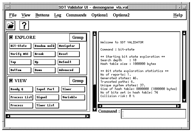
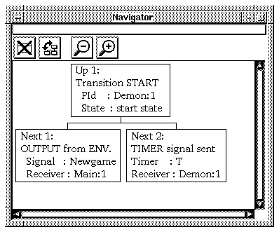
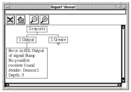
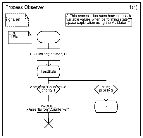
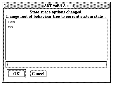