 Table of Contents
  Previous Chapter 22 The SDT Organizer
This section describes the menu bar of the Organizer's Main window and all the available menu choices.
Previous Chapter 22 The SDT Organizer
This section describes the menu bar of the Organizer's Main window and all the available menu choices.
The menu bar contains the following menus:
There are two concepts affecting the menu choices that are available in the menu bar: long/short menus and licence dependent menu choices.
The user can choose between long and short menus with the menu choice View Options in the View menu. Menu choices in short menus are used for editing and simulating. Menu choices in long menus are used for generating code and handling file connections. (File connections are handled automatically by default.)
The following menu choices are only visible in long menus:
The following menu choices are only available if the SDT tool used is available according to the licence configuration:
--------------------------------------------------------------
Licence         Affected menu choices
--------------------------------------------------------------
Code Generator  Make
Simulator       Simulator UI (available with long menus only).
Validator       Validator UI (available with long menus only).
--------------------------------------------------------------
Figure 217 : The File Menu.
-----
(fig)

-----
The File menu features the following menu choices:
This menu choice creates a new system file.
If a system file already is open in the Organizer, the behavior is determined by the status of the existing system structure. If the information is not modified, the New dialog is issued (see below). If modified information exists, the user first gets the possibility to save it; see "The Save Before Dialog" on page 1075.
The following dialog is opened:
Figure 218 : The New Dialog.
-----
(fig)

-----
- Source Directory
- Target Directory
The source directory specifies where new diagrams are saved by default. The target directory specifies where to put generated files. If not set, the directory where SDT was started from is used for both directories. The directories can be changed later; see "Set Directories" on page 1077.
Source and target directories are saved in the system file.
- Root Diagram Type
The type of the root diagram of the new system is selected with this option menu. The default is a system diagram.
If the chosen diagram type is MSC, the diagram will appear in the Associated Documents area. All other types of diagrams will be placed in the Diagram Structure area.
- Root Diagram Name
The name of the new root diagram. The default is "Untitled."
- New
Creates the system file in memory. If the preference MixedPlatform is on and the preference Drives is set to a file, the file is read and inserted as the Drives Section in the newly created system file.
The user has to save the system file to save it on disk. The old contents of the drawing area is replaced with the new root diagram. If any of the diagrams managed by the Organizer were opened in an Editor, these Editor windows are closed.
The settings made in the dialog are preserved as default values the next time the dialog is invoked.
This menu choice opens an existing system file.
If a system file already is open in the Organizer, the behavior is determined by the status of the existing system structure. If the information is not modified, the Open dialog is issued (see below). If modified information exists, the user first gets the possibility to save it; see "The Save Before Dialog" on page 1075.
The Open dialog is a Standard File Selection Dialog, with the file filter set to *.sdt.
The Open button in the dialog opens the specified system file. The old contents of the drawing area is replaced with the new diagram structure. If any of the diagrams managed by the Organizer were opened in an Editor, the Editor windows are closed.
--------------------------------------------------------------------------
Note:
A diagram cannot be opened by the Organizer. If the user specified
a diagram created with an earlier version of SDT, the user is sug
gested to import this diagram in order to create a diagram structure.(fig)
--------------------------------------------------------------------------
The following information consistency checks are performed when opening a system:
- That the opened file is a valid system file. The case when an SDT-2 diagram file is opened is discussed above.
- A comparison of files in the system file and the actual files concerning existence and modification date. A newer physical file will cause this file to be read, to ensure correct references.
- The same checks made as for the Check Files command (see page 1078).
- File protection of the system file and the working directory. If either of them is write protected, a warning message appears.
This menu choice saves all modified diagrams known to the Organizer and finally the system file used by the Organizer. The menu choice is dimmed if the Organizer contains a new system with no corresponding files.
If the system file is modified and in need of saving, an asterisk `*' is appended to the name of the system file in the Organizer's title bar.
When the first diagram that is modified is encountered in the Organizer's view of files, the Save dialog below appears. If not Save All, Quit All or Cancel is selected, the dialog will remain on the screen and all modified diagrams will be handled by the dialog subsequently.
Whether the diagram is connected to a file or not will affect the layout and behavior of the Save dialog. For any unsaved and unconnected diagrams found, the user must provide a filename to connect to.
The appearance of the dialog if the diagram is already connected:
Figure 219 : The Save Dialog When Connected.
-----
(fig)

-----
The appearance of the dialog if the diagram is not connected:
Figure 220 : The Save Dialog When Unconnected.
-----
(fig)

-----
The system file is handled regardless if it is modified or not. If it is modified, the first text row in the dialog is "System file is modified." If not, the text is "System file is not modified, save anyway?" thus allowing the user to save the system file under a different file name. If the system never has been saved, the Organizer proposes a name for the system file; prefix is the name of the first diagram in the structure, suffix is .sdt.
-----------------------------------------------------------------------
Note:
If the system file is saved and the preference MixedPlatform is on,
a check is made that all paths written into the system file has a cor
responding entry in the drive table. A warning dialog is shown if that
is not the case.(fig)
-----------------------------------------------------------------------
The fields and buttons in the Save dialog are:
- Save in File
If the diagram is connected, the name of the connected file is shown. If the system file is to be saved, the name of the system file is shown. The file name can be edited by the user.
If the diagram is not connected, the Organizer proposes a filename based on the diagram name and a file extension corresponding to the diagram type, making the file name unique in the file system (see "Default file names" on page 1190 for more information). The filename can be edited by the user.
The Organizer will not accept any file name that is already opened in an Editor.
The user is prompted to confirm the name if it is already used by a diagram included in the diagram structure.
If the file exists in the file system when the Save button is pressed, the user is warned in a message box that the existing file will be overwritten:
Figure 221 : The Overwriting Dialog.
-----
(fig)

-----
- Clicking Overwrite overwrites the file if file protection allows it and returns to the original Save dialog.
- Clicking Cancel returns to the original Save dialog and the user can provide a new filename.
If a valid filename is provided, Save or Save All below also connects the diagram to the supplied file.
Save
Saves the diagram file. Then shows the next file which needs to be saved.
No Save
Ignores the file without saving it. Then shows the next file which needs to be saved. If, during the save process, the user saves some files but not others, there is a risk of diagram structure mismatches between the system file and the diagram files. Therefore, the following warning dialog is opened:
Figure 222 : The No Save Dialog.
-----
(fig)

-----
- Clicking Ignore does not save the file and continues with the next file.
- Clicking Cancel returns to the original Save dialog to allow the user to save the file.
Save All
Saves all files (diagram files and the system file) without a confirmation by the user, with the exception of unconnected files, which causes the dialog to appear again.
Quit All
Quits all files (diagram files and the system file) without saving. If, during the save process, the user saves some files but not others, there is a risk of diagram structure mismatches between the system file and the diagram files. Therefore, the same kind of warning dialog as for No Save is opened (see above).
Figure 223 : The Quit All Dialog.
-----
(fig)

-----
OK
This button, when clicked as response to an Exit operation, completes the exit process without saving any more diagrams / files.
Cancel
Aborts the save process (possibly the exit process) completely.
Some operations in the Organizer need to save information before the actual operation can be performed. The saving is only performed if modified information exists in the system. In such cases a Save Before dialog is opened, which is very similar to a normal Save dialog. The dialog title is "SDT Save before <command>" and some buttons may behave differently (see Figure 219 on page 1071). If not Save All, Quit All or Cancel is selected, the dialog will remain on the screen and all modified files will be handled by the dialog subsequently.
The Save Before dialog is opened for the following menu choices:
- File menu: New
- File menu: Open
- File menu: Close System
- File menu: Compare System
- File menu: Import Diagrams
- File menu: Exit
The save process handles modified diagrams in the Diagram Structure area and the Associated Documents area. In the case of Exit, unsaved diagrams in Editors that are not yet in the diagram structure of the Organizer are also handled.
If a diagram is modified, has a diagram substructure and some of these diagrams are either opened in an Editor or connected to a file, special care must be taken. If the user chooses not to save such a diagram, inconsistencies between the system file and the diagram files may result. The user is warned in a dialog and may choose to continue, i.e. not to save, or to return to the Save Before dialog. (See "No Save" on page 1073 and "Quit All" on page 1074.)
If the user clicks Cancel in the Save Before dialog, control returns to the Organizer without invoking the requested operation.
- Generate menu: Analyze
- Generate menu: Make
The save process handles modified diagrams in the Diagram Structure area.
The buttons No Save and Quit All are dimmed. If the user clicks Cancel, control returns to the Organizer without invoking the requested operation.
- Generate menu: Convert to PR
The save process handles modified diagrams in the Diagram Structure area, or a selected and modified associated document.
The buttons No Save and Quit All are dimmed. If the user clicks Cancel, the Convert to PR dialog is opened with the GR source diagram toggle dimmed.
- Generate menu: Generate SDL Overview
The save process handles modified diagrams in the Diagram Structure area.
The buttons No Save and Quit All are dimmed. If the user clicks Cancel, control returns to the Organizer without invoking the requested operation.
When selecting any of the Generate commands Analyze, Make, Convert to PR or Generate SDL Overview, the Save Before dialog does not appear if the preference AutoSaveBefore is set. However, unconnected and modified diagrams still require user interaction. If such diagrams exists, the dialog appears.
This menu choice closes the currently opened system and clears the drawing area of the Organizer.
If modified information exists in the current system structure, the user gets the possibility to save it; see "The Save Before Dialog" on page 1075. If any of the old diagrams were opened in an Editor, the Editor windows are closed.
This menu choice prints some or all of the diagrams in the Organizer.
The menu choice starts The Print Utility; for more details on its user interface and the various options, see "Print from Organizer" on page 1444.
This menu choice sets the source and target directories. For more information on these directories, see "Source Directory" and "Target Directory" on page 1057.
If the source directory is changed while a Save dialog is active in an Editor, the directory where the Editor saves the diagram is undefined. An ongoing analysis is not affected by changing the target directory. Simulators and validators must be restarted in order to use a changed target directory.
Figure 224 : The Set Directories Dialog.
-----
(fig)

-----
- Source Directory
- Target Directory
If the directories are already set, the current settings appear as default values. If a directory is not specified, the directory where SDT was started from is used.
Source and target directories are saved in the system file.
- Show absolute path
If this option is set (the default), the Organizer shows and stores diagram files with full path.
- Show path relative to Source Directory
If this option is set, the Organizer shows and stores diagram files with paths relative to the source directory. The path is not stored for file connections that match the Source Directory path.
This menu choice displays the drive table of the currently opened system, i.e. the mapping between disk drive names in MS-DOS and the beginning of corresponding directory paths on Unix. The menu choice is only available if the preference MixedPlatform is on. For more information, see "MS-DOS and Unix File Compatibility" on page 1152.
The following dialog is opened:
Figure 225 : The Set Drives Dialog.
-----
(fig)

-----
The text area displays the drive table currently used in the system. The table can be edited directly in the text area. When the system file later is saved, the table is stored in the Drives Section.
When clicking OK, a basic syntax check is performed on the entered drive table. Each line should consist of two items only:
- An MS-DOS disk drive letter followed by a colon, e.g. h:
- A Unix directory path starting with a slash `/'.
If any errors are found, the user is notified and the dialog is not closed. If the table was changed and found to be syntactically correct, the system file is marked as modified.
This menu choice verifies all file bindings and diagram structures in the Diagram Structure area and in the Associated Documents area.
For each file, the menu choice checks if the file exists and if the file is an SDL diagram file. If not, the status is logged in the Organizer Log window and the diagram icon is marked Invalid. However, the file does not have to be of the correct type when checked. In this case the information is logged, but the user may continue working with the diagram.
If a diagram is marked invalid, the user must later correct the file binding. The user could either reconnect the diagram to a valid file, or perform a disconnection in which case the diagram disappears.
The diagram structures in the system file and in the diagram files are also compared, in terms of existing SDL reference symbols. If connected diagrams in the system file are not present in the corresponding diagram files, the diagram icons are marked Mismatch and the status is logged in the Organizer Log window. Unconnected diagrams are removed from the system file and the Organizer's diagram structure. New reference symbols found in the diagram files are added as unconnected diagrams in the system file and the Organizer's diagram structure.
If a diagram is marked mismatched, the user must later correct the diagram structures. The user could either perform a disconnection in which case the diagram disappears, or change the appropriate diagram in an Editor to include the mismatched reference symbol.
This menu choice compares the contents of the Organizer Main window with the contents of a system file (.sdt file).
The two structures are compared and possible differences are reported to the user, with the option to merge the two structures, by specifying which diagrams to add and which to remove. The merged results are applied to the Organizer (with the possibility to save the results).
The information is processed according to the following scheme:
- First, the user is asked to exit any SDL and MSC Editor, if any is found running.
- Then, the user is prompted to save modified diagrams and / or system file in a Save Before Dialog.
- Then, a Standard File Selection Dialog is issued, where the system file to compare the Organizer view with may be selected. Once the system file of the user's choice is selected and the OK button is pressed, the comparison is started.
- The Compare System dialog is issued, where the differences are reported (if the Organizer view and the contents of a system file are found identical, this is reported in a message box and the operation is terminated).
Figure 226 : The Compare System Dialog.
-----
(fig)

-----
- The user decides if and how to merge the two views, by selecting / deselecting the diagrams to include or exclude from the resulting Organizer view.
- Clicking the OK button updates the system by including / excluding diagrams as specified in the dialog
- Clicking Cancel closes the dialog without updating the system.
The Compare System function will now be described in detail.
- The Compare System dialog has two lists, allowing multiple selection. Each list is scrollable horizontally and vertically (the lists are scrolled vertically accordingly, in order to align items that represent the same diagram).
- The lists are sorted according to the order of appearance of the diagrams in the Organizer Main window.
- Each item in a list identifies a diagram that was found in only one of the two structures (i.e. in the Organizer or in the system file) or were found in both structures, but differ from each other (see "How Systems are Compared" on page 1082 for more information about how structures and diagrams are compared).
A diagram is listed with its type, name and the file it is stored on.
- A diagram that was found in one structure but missing in the other structure is present in one list only and being identified in the other list with a non-selectable `-' (hyphen)
- Diagrams that were found in both structures and are considered equal (see page 1083) are not listed
- Diagrams that were found in both structures and are considered almost equal (see page 1083) are present in both lists.
- Diagrams that are selected will be included in the resulting (merged) Organizer view.
The diagrams that are listed here are the diagrams that were found in the Organizer's Diagram Structure or Associated Documents areas.
(where <system file> corresponds to the directory and name of the selected system file)
The diagrams that are listed here are the diagrams that were found in the system file.
- By default, given two diagram that are considered almost equal, the dialog will select the diagram originating from the Organizer, not the diagram originating from the system file. See example in Figure 227, above.
This subsection provides additional information about the rules that govern how systems are compared.
- Relative file names:
Relative file names are managed as if they were relative to the Source Directory as currently specified in the Organizer.
- Handling of SDL diagrams (including packages, excluding macro diagrams):
Diagrams in a tree structure are examined starting from the top and down. When two diagrams are found to differ, their diagram subtree is not examined further, the subtrees being considered as a part of the diagrams that differed.
This means that if the user chooses to include a diagram that has a subtree, the complete subtree will also be included. Similarly, if the user chooses to exclude a diagram that has a subtree, the complete subtree will be excluded.
The level of indentation used when listing diagrams in the dialog indicates the structural level at which a diagram is found.
- Handling of Message Sequence Charts, SDL macro diagrams and SDL overview diagrams:
Since these diagrams cannot be part of a subtree, adding or removing any of these does not affect the remaining parts of the structure.
- Rules for equality of diagrams
Two diagrams may be considered equal or almost equal.
- equal
Diagrams are considered equal if the diagram type, name and file name are equal (equal diagrams are not listed in the dialog).
- almost equal
Diagrams are considered as almost equal if the diagram type and name are equal but not the file name. Two diagrams that are almost equal are presented on one line in the dialog. For root diagrams it is possible to select both diagrams on one line in the dialog. For non-root diagrams it is only possible to select one of the diagrams.
-------------------------------------------------------------------
Note:
Compare System does only compare the structural system informa
tion saved in the system file. Compare System does not compare the
diagram contents, such as page names.
-------------------------------------------------------------------
The Compare System function preserves, as long as possible, the links between the diagrams in the Associated Documents area and the diagrams in the Diagram Structure area.
- When a link is found in a system file, the file name of the diagram in the Diagram Structure area is saved along with the diagram in the Associated Documents area.
- If a diagram in the Associated Documents area is selected by the user to be included in the Organizer, SDT generates a link, if a diagram with the previously saved file name can be found in the Diagram Structure area.
This menu choice imports a diagram or a number of diagrams in SDT2 or SDT-3 format, and extracts the diagram structure with the possibility to save it on a system file. The command may, on demand, convert the imported diagram into SDT3 format without the need to involve the user for each diagram to convert.
To avoid potential name conflicts when saving an imported diagram structure, the menu choice will not perform any action, and causes the following message box to be displayed in the case any files are opened in an Editor.
Figure 228 : Import Diagrams Disabled.
-----
(fig)

-----
Basically, the involved SDL diagrams and their corresponding files are bound and the file bindings are put in the system file (not saved on disk). A number of information entities are also extracted from the diagrams.
If a system file already is open in the Organizer, the behavior is determined by the status of the existing system structure. If the information is not modified, the Import Diagrams dialog is issued (see below). If modified information exists, the user first gets the possibility to save it; see "The Save Before Dialog" on page 1075. If any of the old diagrams were opened in an Editor, these Editor windows are closed.
The following dialog is opened:
Figure 229 : The Import Diagrams Dialog.
-----
(fig)

-----
The root diagram to import and convert can either be named logically with type and name, or physically with a file name. The user can toggle between diagram type/name and diagram file. The specified diagram will become a new root diagram in the Organizer. The imported diagrams are placed in the Diagram Structure area.
This menu choice deletes one or more system files from the file system.
A Standard File Selection Dialog is opened with the file filter set to *.sdt. The file is deleted when the OK button is clicked.
It is possible to delete the system file corresponding to the current system in the Organizer. This does not affect the current system, i.e. the user can later save the system in a new system file.
The Standard File Selection Dialog may be used for deleting any file, however diagram files that are loaded in an Editor may not be deleted.
This menu choice exits the Organizer.
The exiting process consists of four phases:
- Handling of modified files managed in the Organizer structure.
If modified information exists in the current system structure, the user gets the possibility to save it; see "The Save Before Dialog" on page 1075. The dialog is opened for the first file (diagram/system file) that is modified in the Organizer's view of files. The user can then choose how to continue. If the user does not select Save All, Quit All or Cancel, the dialog will remain on the screen and all modified files will be handled by the dialog subsequently.
The system file is saved last, if necessary. If the Exit process at a later stage is cancelled, all diagrams in the Editors are still available, since they are not closed until all modified diagrams are handled.
- Confirmation of Exit
When no print, analyze, make or validation jobs are active, the confirmation of Exit looks like this:
Figure 231 : Exit Confirmation Without Active Jobs.
-----
(fig)

-----
If there are such active jobs, the user gets the possibility to force an exit of these jobs:
Figure 232 : Exit Confirmation With Active Jobs.
-----
(fig)

-----
- Removing of diagrams in Editors
- Shutdown of tools
All SDT tools are terminated, possibly issuing a "Save before exit" dialog. Finally, the Organizer itself is terminated.
A general mechanism to edit the diagram structure(s) in the Organizer does not exist. Some of the menu choices in the Edit menu are used for basic operations on root diagrams and file connections. However, most changes to the diagram structure are a result of operations made in the diagram Editors; see "Reference Symbols" on page 1176.
Figure 233 : The Edit Menu.
-----
(fig)

-----
The Edit menu features the following menu choices:
This menu choice edits the selected diagram/page by starting/loading a corresponding SDL Editor or MSC Editor. These tools are described in "The SDL Editor" on page 1153 and "The MSC Editor" on page 1297.
The menu choice is dimmed if the selected icon is invalid, or if an instance or dashed diagram icon is selected.
The operation performed depends on the type of diagram:
The settings made in the dialog are preserved as default values the next time the dialog is invoked.
This menu choice starts an SDL Editor with the diagram and page that references the selected diagram. The reference symbol is shown selected in the Editor window.
The menu choice is dimmed if:
- There is no selection
- A root diagram is selected in the diagram structure tree
- The reference icon is marked invalid
- The selected diagram is not connected
- An associated document link is selected
- An icon in the Associated Documents area is selected
This menu choice adds a diagram at the root level or to the Associated Documents Area. To add other SDL diagrams on other levels, the SDL Editor is used (see "Add of a Reference Symbol" on page 1177 in The SDL Editor chapter). The menu choice is dimmed if there is no system opened in the Organizer.
The following dialog is opened:
Figure 235 : The Add Diagram Dialog.
-----
(fig)

-----
- As Diagram Structure Root
This option adds the diagram as a root diagram in the Diagram Structure Area. Selecting an MSC or Overview diagram will cause an error message to appear if Add or Add & Connect is clicked. After confirming the message box, control is returned to the Add Diagram dialog.
- As Associated Document
This option adds the diagram in the Associated Documents area.
- Diagram Type
The type of diagram to be added is selected with this option menu. The default is Package diagram.
- Diagram Name
The name of the diagram to be added is specified in the input field. The default is "untitled." Multiple root diagrams with the same name are allowed.
- Add
Adds the diagram to the chosen presentation area as an unconnected diagram.
- Add & Connect
Adds the diagram to the chosen document area as a connected diagram. The Connect Diagram dialog appears, see "Connect Diagram" below. The diagram is added as an unconnected diagram before this dialog, so clicking Cancel in the dialog only cancels the connect operation.
The new diagram is placed as a root diagram in the structure according to the diagram ordering scheme (see "Ordering" on page 1064).
If a diagram in the Diagram Structure area was selected and an MSC or Overview diagram is added, an associated documents link is automatically added to the selected diagram.
This menu choice removes the selected root diagram and its diagram substructure, if any, from the system structure. It can be applied on root diagrams in the Diagram Structure area and on diagrams in the Associated documents area. The menu choice is dimmed if such a diagram is not selected, or if the diagram is modified.
For a diagram in the Diagram Structure area, the following dialog is opened:
Figure 236 : The Remove Diagram Dialog.
-----
(fig)

-----
For a diagram in the Associated Documents area, the following dialog is opened:
Figure 237 : The Remove Associated Document Dialog.
-----
(fig)

-----
This menu choice connects a selected diagram to a file. It is not visible if the user has chosen short menus (see "Available Menu Choices" on page 1067). It is possible to reconnect an already connected diagram.
The menu choice is dimmed if a page, instance diagram, or dashed diagram icon is selected.
The following dialog is opened:
Figure 238 : The Connect Diagram Dialog.
-----
(fig)

-----
- To an existing file
This option connects the diagram to an existing file. The filter in the associated file selection dialog corresponds to the file extension for the diagram type. When the connection is to be made, a check is made on the selected file. If the file is not an SDL or MSC file, an error message box is issued.
Figure 239 : The Connect Error Message.
-----
(fig)

-----
If the file contains a diagram which has an incorrect name or type, the user is warned in a dialog:
Figure 240 : The Connect Warning Dialog.
-----
(fig)

-----
- Clicking Connect connects to the file anyway.
- Clicking Cancel aborts the connection and returns control to the Connect Diagram dialog.
By expanding diagram in search list
This option connects the diagram according to the search path found in a search list file.
Expand Diagram Structure
This option recursively expands and connects diagrams to files until no more reference symbols are found. After the expansion is completed, the Organizer display is updated.
This option is dimmed if an associated document was selected.
Expand Package References
If a diagram has a USE clause, i.e. it references a package diagram, this option tries to expand the package and put it as a root diagram in the system. The diagram substructure of the package is expanded. Package references are expanded recursively.
The option is dimmed when performing a reconnect to an already connected file or if an associated document was selected.
Search List File
The search list file to read from. The filter in the associated file selection dialog is *.ssl. The default file is sdt.ssl.
Connect
Performs the connection and expansion according to the options.
Connect & Edit
Performs the connection and expansion according to the options. When completed, the diagram (or root diagram if expanding) is opened in an Editor.
If a connection is made in the Diagram Structure area to a file which appears in the Associated Documents area, the corresponding associated document icon is removed.
If an error occurs, the user is informed in a message box and control is returned to the Connect Diagram dialog.
If the dialog was invoked from the Add Diagram dialog and the diagram was to be added in the Associated Documents area, the two Expand options are dimmed.
When performing a reconnect to an already connected diagram, the current diagram references are matched against those found in the connected file. If mismatches are found, icons are marked as such but the structure is kept intact, if possible.
When connecting an unconnected diagram that is opened and unsaved in an Editor, the file name binding is not conveyed to the Editor, i.e., the Editor binding is lost.
It is not possible to connect a diagram to a file that is already open in an Editor.
Figure 241 : Attempt to Connect a Diagram to an Open File.
-----
(fig)

-----
If the user specifies to connect By expanding diagram in search list and to Expand Diagram Structure and the Organizer encounters a file that already is open in an Editor or that cannot be found using the search list, the connection is not made for this file (and its substructure). The connection continues for the rest of the diagrams, however.
This menu choice disconnects the connected file from the selected diagram. It is not visible if the user has chosen short menus (see "Available Menu Choices" on page 1067).
The menu choice is dimmed if the selected diagram is not yet connected, or if a page, instance diagram, dashed diagram, or an associated document icon is selected.
The following dialog is opened:
Figure 242 : The Disconnect Diagram Dialog.
-----
(fig)

-----
If the diagram is currently loaded in an Editor and is modified, the diagram reference in the Organizer gets the same status as if a new diagram is edited, i.e. new and unconnected. There are two cases:
- If the diagram is placed in the Diagram Structure area, an identical diagram icon is added to the Associated Documents area, keeping the existing file connection and Editor binding.
- If the diagram is placed in the Associated Documents area, the Editor binding is lost.
This menu choice opens a file associated with an SDT reference in an appropriate window:
- If the SDT reference is a GR reference, the corresponding diagram is opened in an SDL or MSC Editor and the symbol associated with the GR reference is highlighted.
- If the SDT reference is a file reference, the referenced file is opened in the Organizer's Text Viewer.
For more information on SDT references, see "References in SDT-3" on page 2473.
The following dialog is opened:
Figure 243 : The Go To Source Dialog.
-----
(fig)

-----
- SDT Reference
The textual SDT reference is specified in the input field.
- Go To
Shows the symbol in an Editor, or the text file in the Text Viewer.
An error message appears if the format of the SDT reference is incorrect or if the requested SDT reference cannot be found.
This menu choice associates or deassociates a selected document in the Associated Documents Area with a diagram in the Diagram Structure Area. The menu choice is dimmed if no MSC or Overview diagram in the Associated Documents area is selected, or if the selected diagram is not connected.
The selected document originates from the Associated Documents area, but this menu choice works as well if the document reference is selected in the Diagram Structure area (a re-association). It is only possible to have one link to an associated document.
The following dialog is opened:
Figure 244 : The Associate Document Dialog.
-----
(fig)

-----
- No association
This option clears the association link to the diagram selected in the list.
- Associate <type> <name> with
The type and name of the document to associate. This option adds an association link to the diagram selected in the list.
- OK
Associates/deassociates the document with the diagram selected in the list. An Associated Document Link is added/removed in the Diagram Structure area.
This menu choice checks the diagram Kernel Heading Symbols for correctness with respect to what is defined in the Organizer's Diagram Structure area.
It operates on the selected diagram and its substructure. If no diagram is selected, all diagrams in the Diagram Structure area are checked.
Before the kernel headings are checked, a check is made to see if any file is connected to more than one diagram. Such files are reported in the Organizer log, and a warning box is issued to the user. These files may be modified for each appearance and will cause all but the last update to be incorrect.
The kernel heading check is made silently until the first incorrect heading is found. The diagram checked is then shown in the dialog below. If an incorrect qualifier is found, the user is prompted in the dialog whether to update the header or not. The user also has the possibility to silently update all incorrect headings. That is, they are loaded into an SDL Editor and are then corrected without confirmation by the user.
After the operation, all updated headings are in an unsaved mode in the Editor.
This operation should be done regularly in order to avoid peculiar and hard-to-find analysis error caused by incorrect diagram headings.
Qualifiers could be placed in other symbols than the heading in the system, such as qualifying data types in a text symbol. Such qualifiers are not found by the Update Headings menu choice.
The following dialog is opened:
Figure 245 : The Update Headings Dialog.
-----
(fig)

-----
- Current kernel heading
A read-only text field that shows the contents of the Kernel Heading Symbol as defined in the SDL diagram (i.e. what is displayed in the SDL Editor).
- Correct kernel heading
A read-only text field with the correct heading according to the structural location of the diagram.
- Update
Updates the kernel heading in the SDL Editor. Continues to search for the next incorrect heading and keeps the dialog open. When the updating is completed, a message appears in the status bar.
- No Update
Does not update the SDL diagram's kernel heading. Continues to search for the next incorrect kernel heading and keeps the dialog open.
- Update All
Updates all kernel headings without a confirmation by the user and closes the dialog. When the updating is completed, a confirmation message is shown in the status bar.
Figure 246 : The View Menu.
-----
(fig)

-----
The View menu features the following menu choices:
This menu choice expands the diagram structure tree one level down for the selected diagram.
The menu choice is dimmed if:
- No diagram is available or selected in the Diagram Structure Area
- The selection is in the Associated Documents Area
- The selected icon is a leaf (no children icons)
- The selected diagram is not connected
- The selected icon is marked invalid
- The selected icon is already expanded
This menu choice expands the diagram structure tree the whole way down for the selected diagram.
The menu choice is dimmed for the same reasons as Expand above.
This menu choice expands the diagram structure trees the whole way down, i.e. all diagrams are shown.
This menu choice hides all diagrams below the selected diagram in the Diagram Structure Area.
The menu choice is dimmed if:
A collapsed diagram does not affect a corresponding diagram file opened in an Editor, i.e. it does not have to be closed or saved.
A collapsed diagram has a small triangle drawn below the diagram icon to indicate that it is collapsed.
This menu choice sets options for controlling the appearance of the Organizer window, as well as options for which icon attributes to show.
The options are set in a modeless dialog, i.e. the Organizer can continue working without waiting for the dialog to be closed. The options are saved in the system file.
The following dialog is opened:
Figure 247 : The View Options Dialog.
-----
(fig)

-----
The items in the View Options dialog is grouped into the following sections. The figure above shows the default settings. The settings made in the dialog are preserved as default values the next time the dialog is invoked.
The Tree Mode section contains options for the two different tree presentation modes available for the Diagram Structure area (see "Presentation Modes" on page 1059).
The Menu mode section contains options for which menu choices that are available (see "Available Menu Choices" on page 1067).
The Show Sections section contains options for which parts of the main window to show.
The Show section contains options for which diagrams and file attributes to show.
- Diagram type names
Show/hide the type of the diagram in textual form, e.g. system, Block, etc. The text is placed to the left of the diagram name.
- Diagram virtuality
Show/hide the virtuality of a diagram in textual form. Only applicable to type diagrams.
- Diagram file names
In list mode: Add/remove a column of associated file names to the Diagram Structure area.
In tree mode: Add/remove a line of text with the associated filename under each node in the diagram structure tree. The texts do not overlap; diagram symbols are separated to make space for the full text.
If a diagram is not connected to a file, [unconnected] is shown.
- Diagram directories
Complements the Diagram file names option above.
Add/remove the directory path of the associated files to the Diagram Structure area, in the same location as Diagram file names. If the Diagram file names option is set, the directory path is added in front of the file name. The path added is determined by the Source Directory option; see "Set Directories" on page 1077.
- Instance diagrams
Show/hide instance diagrams in the Diagram Structure area.
- Dashed diagrams
Show/hide dashed diagrams in the Diagram Structure area.
- Associated document links
Show/hide associated document links in the Diagram Structure area.
- Pages
Show/hide pages in the Diagram Structure area.
- Separators
Hide/show separators in the Diagram Structure area. Separators show how the generated code will be separated into different files. The lines between diagrams are broken by two vertical or horizontal bars where the separations occur.
Figure 248 : Separators in Diagram Structure Area.
-----
(fig)

-----
- Apply
Applies the changes in the dialog settings to the Organizer's view, but does not close down the dialog.
- Default
Resets all options in the dialog to the state they were in when the dialog was opened.
- Close
Closes down the dialog, without applying any changes made since the last Apply.
This menu choice sets the scale used in the Organizer window.
The scale is set using a modal dialog:
Figure 249 : The Set Scale Dialog.
-----
(fig)

-----
The scale could be set between 20% and 800% by using the slider. 100% is the default. The setting is saved in the system file.
Pressing Set changes the scale and brings down the dialog.
Figure 250 : The Generate Menu.
-----
(fig)

-----
The Generate menu features the following menu choices:
This menu choice starts the Analyzer for the selected diagram or all diagrams. It is dimmed if:
- A job using the Analyzer is already running.
- An MSC or Overview diagram is selected.
- The selected diagram is not connected.
- The selected icon is marked invalid.
If modified information exists in the current system structure, the user should first save it in a Save Before Dialog; see page 1075.
Any SDL diagram in the Diagram Structure area can be selected for analysis. The diagram will be analyzed in its context and together with its substructure.
If there is exactly one SDL structure defined in the Diagram Structure area (except for additional packages and macros), this structure is analyzed if no diagram is selected. If more than one SDL structure is defined in the Diagram Structure area, a diagram must be selected in order to be analyzed.
Options for the Analyzer are specified in the modal dialog below. The settings are saved in the system file and persist until the next time the dialog is invoked for the same system.
Figure 251 : The Analyze Dialog.
-----
(fig)

-----
Perform a semantic check. It requires Syntactic analysis to be set, otherwise it is dimmed. The additional semantic check options below require this option to be set; otherwise they are dimmed. They are also dimmed if a system or package was not the target for the analysis. For more information on these options, see "Performing Semantic Check" on page 314 and in chapter 6, Verifying a System.
- Check output semantics
- Check unused definitions
- Check references
- Generate a cross reference file
Generate a cross reference file when performing the analysis. In the text field, a file name is proposed with the diagram to be analyzed as prefix and .xrf as suffix. The filter in the associated file selection dialog is *.xrf. The file is by default generated in the Target Directory.
If this option is selected and if no file is specified, the user is warned in a message box. No generation is performed and control is returned to the Analyze dialog.
If a user-specified file already exists, the following dialog appears:
Figure 252 : The Overwrite Dialog.
-----
(fig)

-----
The Overwrite button starts the generation and overwrites the file. The Cancel button returns to the Analyze dialog.
Error limit
The error limit before aborting the analysis (0 - 1000). A limit of 0 (zero) means that there is no error limit.
Log expressions deeper than
The performance of the Analyzer depends to a large extent on the depth of the SDL expressions to be resolved. This option is used to emit warnings when the depth of an expression exceeds a certain value (0 - 1000). A limit of 0 (zero) means that no warnings will be issued.
System instances
This text field specifies the system instances to be analyzed if more than one system instance exists. The field should contain the qualifiers of the blocks whose process definitions are to be analyzed, instead of any substructure definitions in those blocks. For an example of a specification, see "Specifying a System Instance" on page 315.
The options above are forwarded to the Analyzer when the analysis process starts.
- Analyze
Starts the Analyzer in the background and closes the dialog. Status information from the ongoing analysis is shown in the Organizer Log window.
- Full Analyze
Has the same effect as the Analyze button, except that it forces the entire system to be analyzed
- Set
Saves the Analyzer option settings and closes the dialog, but does not perform an analysis.
This menu choice makes a system, i.e. generates code for it and optionally compiles and links it. The menu choice is not visible if the user has chosen short menus (see "Available Menu Choices" on page 1067). It is dimmed if:
- A job using the Analyzer is already running
- There is no system diagram in the Diagram Structure area
- The selected diagram is not connected
- The selected icon is marked invalid
If modified information exists in the current system structure, the user should first save it; see "The Save Before Dialog" on page 1075.
If there is exactly one SDL structure defined in the Diagram Structure area (except for additional packages and macros), this structure is considered as the source for Make. If more than one SDL structure is defined in the Diagram Structure area, a system diagram must be selected in order to perform Make.
Options for the Make process are specified in the modal dialog below. An analysis phase is executed as part of the Make process. The existing Analyzer options as set in the Analyze dialog are used.
Figure 253 : The Make Dialog.
-----
(fig)

-----
By default, all generated files are stored in the Target Directory.
- Analyze & generate code
This option generates code, and performs an analysis if necessary. If not set, the settings below do not affect the Make process.
- Code generator
The code generator is selected with this option menu. The following code generators are supported to date:
- Prefix
The type of prefix for variables is selected with this option menu: Full (default), Entity Class, No or Special. For more information, see "Prefixes" on page 2038.
- Separation
The type of modularity is selected with this option menu: No (default), Full or User Defined. For more information, see "Selecting File Structure for Generated Code - Directive #SEPARATE" on page 2020.
- Capitalization
The type of capitalization is selected with this option menu: Lower Case (default) or First Occurrence. For more information, see "Case Sensitivity" on page 2040.
- Generate environment header file
If this option is set, a header file is generated containing the definitions of the SDL system's interface to the environment. For more information, see "System Interface Header File" on page 453.
- Enable partitioning
Enables the system to be partitioned into multiple executables at a later stage. This option corresponds to the SDT-2 directive #PART. If the system is an imported SDT-2 system, this option is initially set (see "Extract code generator directives" on page 1087).
- Compile & link
This option compiles and links by executing the makefile. If not set, the settings below do not affect the Make process.
- Generate makefile
Generate a makefile (default). The file is given the name SDTMake.m and is created on the directory specified as Target Directory (see page 1077).
- Generate makefile and add template file
Generates a makefile and appends the specified, user defined, template at the end of the makefile. Two "hooks" are provided in the generated part of the makefile: USERTARGET and USERLIBRARIES. This enables the user to define his own targets as well as adding properties in the make file. The recommended file name extension for a template file is .tpm.
In the template file, USERTARGET is used to add additional object files to the link script in the generated make file, by defining this name as a list of object files.
In the template file, USERLIBRARIES is used to add library modules, for example -lm or -lsocket, to the link script in the generated make file, by defining this name as a list of libraries.
The template file can also contain the compilation scripts for the object files specified as USERTARGET.
Example 28 : Contents of Make Template File
USERTARGET = sctenv$(sctOEXTENSION)
USERLIBRARIES = -lm -lsocket
# Dependencies and actions
sctenv$(sctOEXTENSION): sctenv.c
        $(sctCC) $(sctCPPFLAGS) $(sctCCFLAGS) \
        $(TARGETDIRECTORY) sctenv.c \
        $(sctIFDEF) -o sctenv$(sctOEXTENSION)
- Use makefile
Specifies an existing makefile to use.
- Standard kernel
Use one of the available standard kernels. The kernel is selected from this option menu. The available kernels depend on the licence configuration. The following kernels are available (the default is Application):
- Use kernel in directory
Specifies a non-standard kernel to use. The user should specify the directory where the actual kernel file is stored.
- Make
Starts the generation in the background and closes the dialog. Status from the ongoing Make process is shown in the Organizer Log window.
- Full Make
Has the same effect as the Make button, except that it forces the entire system to be regenerated, even if only certain parts needs to be regenerated.
- Set
Saves the Make option settings and closes the dialog, but does not perform a make.
- Analyze Options
Opens the Analyze dialog to set the analyze options. The Set button returns to the Make dialog.
This menu choice generates an SDL overview diagram with the selected diagram, or the root diagram, as the top diagram. The menu choice is dimmed if the selected icon is marked invalid.
If modified information exists in the current system structure, the user should first save it; see "The Save Before Dialog" on page 1075.
If there is exactly one SDL structure defined in the Diagram Structure area (except for additional packages and macros), an overview diagram is generated for this structure if no diagram is selected. If more than one SDL structure is defined in the Diagram Structure area, a diagram must be selected in order for an overview diagram to be generated.
By default, all generated files are stored in the Target Directory.
The following dialog is opened:
Figure 254 : The Generate SDL Overview Dialog.
-----
(fig)

-----
- Name of Generated SDL Overview
Specifies the name of the generated Overview diagram. The Organizer proposes a name based on the diagram the Overview is to be generated from. If a user-specified name already exists, the user is warned when the Generate button is pressed. Confirming the warning returns to the Generate SDL Overview dialog.
- Use Expanded Diagrams Only
Controls whether the resulting SDL Overview should comprise all diagrams that are included in the diagram substructure, or only include the diagrams which are expanded (i.e. visible in the Organizer`s Diagram structure).
- Include Procedures & Operators
Governs if SDL procedure and operator diagrams should be included in the SDL Overview.
- Include States
Controls whether state symbols should be added to the SDL Overview or not.
- Include Lines
Governs whether lines (such as channels and signal routes) should be added to the SDL Overview or not.
- Minimum Symbol Width
- Minimum Symbol Height
These slide bars control the minimum size the tool will apply on symbols. (Symbols will be shrunk, if required, to fit in the diagram).
- Margin
This slide bar specifies the distance (in any direction) between symbols at one SDL level and the enclosing frame (the boundaries of the enclosing SDL symbol).
- Distance between Lines
- Distance between Symbols
These slide bars define what distance will be inserted between lines that otherwise will overlap each other in the generated SDL Overview diagram.
- Generate
Causes the generation of the overview diagram to start. The user is informed about the progress of the generation in the Organizer Log window. The generated SDL overview is inserted into the Associated Documents area. An SDL Editor opens and presents the Overview diagram.
This menu choice generates a formatted (pretty printed) PR file. Input is either a PR file or a GR diagram structure. The menu choice is dimmed if a job using the Analyzer is already running.
If modified information exists in the current system structure, the user should first save it; see "The Save Before Dialog" on page 1075.
Figure 255 : The Convert to PR Dialog.
-----
(fig)

-----
- Source: <type> <name>
Converts a GR diagram structure to PR. The top of the diagram structure appears in the name of the button.
This option is dimmed in the following situations, in which case the name of the button is "No diagram selected":
- A Referenced Diagram icon or a Referenced Diagram Type icon is not selected. The corresponding diagram must also be connected
- The selected diagram is not connected
- The selected icon is marked invalid
- There is no currently opened system
The range of diagrams to be converted depends on the selection in the Organizer:
- If there is no selection, all diagrams in the Diagram Structure area are converted. If there are more than one root diagram (except for packages and macros), the user is warned when trying to convert and the conversion is aborted.
- If there is a selection, this diagram is converted. If the diagram has an expanded diagram substructure visible in the Organizer, this substructure is also converted. All PR code is put in the destination PR file.
- PR file
Generates a pretty printed PR file from an existing PR file, which is specified in the input field. By default, this file is read from the Source Directory.
- Write reserved words in
Specifies whether reserved words in SDL are to be written in lower case or upper case.
- Expand included PR files
Expands SDL PR include files found in /*#INCLUDE...*/ comments.
- Destination PR file name
Specifies the pretty printed PR file to generate. The default name uses the selected diagram name as prefix and .sdl as suffix. By default, this file is stored in the Target Directory.
If no file name is provided, the user is warned and no conversion is performed.
An Overwrite confirmation dialog is issued if the user changes the suggested file name and specifies a file that already exists.
- Convert
Generates the pretty printed PR file and closes the dialog. Status from the ongoing conversion process is shown in the Organizer Log window.
- Analyze Options
Opens the Analyze dialog to set the analyze options. The Set button returns to the Convert to PR dialog.
This menu choice converts a PR file to one or more SDL-GR diagrams. The menu choice is dimmed if a job using the Analyzer is already running.
Figure 256 : The Convert PR to GR Dialog.
-----
(fig)

-----
- Source PR file name
Specifies the PR file to convert.
- Write reserved words in
Specifies whether reserved words in SDL are to be written in lower case or upper case.
- Expand included PR files
Expands SDL PR include files found in /*#INCLUDE...*/ comments.
- Destination directory
Specifies the directory where to put the generated diagrams. By default, the source directory will be used (see "Set Directories" on page 1077).
- Convert
Generates the GR diagrams. The GR files are named in the same way as when saving unconnected diagrams in the Organizer, i.e. files are named so that no files are overwritten. Status from the ongoing conversion process is shown in the Organizer Log window.
- Analyze Options
Opens the Analyze dialog to set the analyze options. The Set button returns to the Convert to GR dialog.
This menu choice inserts or edits a separation on the selected diagram. It is not visible if the user has chosen short menus (see "Available Menu Choices" on page 1067). It is dimmed if:
- The selected diagram type is not one of system, system type, block, block type, and package
- A valid diagram type is selected, but it is located in the Associated Documents area
Diagram separations are used during code generation and controls both the splitting of the target into separate modules and the naming of these modules. Separations can be shown in the diagram structure of the Organizer; see "Separators" on page 1107. Information about separations are stored in the system file.
Figure 257 : The Edit Separation Dialog.
-----
(fig)

-----
- No separate file
No separation is to be used on this diagram; any existing separation is cleared. This option is disabled on system and package diagrams.
- Separate file
Inserts a separation on this diagram, i.e. the diagram and its substructure is generated separately. In the text field below, the name of the separation is specified, i.e. the prefix of the generated files.
Figure 258 : The Tools Menu.
-----
(fig)

-----
The Tools menu features the following menu choices:
This menu choice searches for text in SDL and MSC diagrams, starting with the selected diagram. The menu choice is dimmed if:
- An Instance Diagram or Dashed Diagram is selected
- The selected diagram is not connected
- The selected icon is marked invalid.
The search will only take place in diagrams that are connected and do not have an invalid status.
The search will start in the selected diagram and continue in top-down order for the rest of the diagrams (the order is left-right in a tree view).
The search function will go through the list of diagrams and stop each time the search criterias, as set in the dialog below, matches. If a search/replace string or any option is changed when the search is stopped (a match is found or the user pressed Abort), these values become the basis when the search is continued.
The search process will open an Editor window, if necessary, and select the matched search text.
The searching is based on ASCII character matching. All text fragments in symbols are searched, with a few restrictions (see below).
The Search dialog is modal, which means that the Organizer is locked for other user input during the search. When all diagrams have been searched, the message Search completed appears in the dialog to inform the user.
Figure 259 : The Search Dialog.
-----
(fig)

-----
The Search dialog contains the following fields and options. The default settings when first invoked are shown in the figure above. Values from the previous invocation is used for settings when the dialog is used again.
When the dialog is first opened, all buttons except Replace&Search and Replace All are enabled. When Search, Replace&Search or Replace All is pressed all fields and buttons are disabled except Abort. If a search string is found in an Editor, it is selected and all buttons and fields are enabled.
When the first search or replace operation has been applied and control returns to the Search dialog, where it is possible to perform a new search on the same diagram(s).
- Search
Searches for the search string. An Editor is opened when the search string is found. If no the text is supplied in the Search for field, a warning message appears. Confirming the message box will return control to the Search dialog.
- Replace&Search
Replaces the current match with the replace string and searches for the next match. An Editor is opened when the search string is found.
- Replace All
Replaces all occurrences of the search string with the replace string. No Editors are opened. However, diagrams with replaced text are loaded in the Editor and gets a "dirty" state in the Organizer.
Text in Reference Symbols and in Kernel Heading Symbols is not replaced.
- Done/Abort
The Done button closes the Search dialog. The Done button is temporarily renamed to Abort during search in diagrams. If Abort is pressed, the current search is stopped as soon as possible (when a new file is to be searched). After an Abort, the dialog remains on screen, ready for new input.
All data in the Editors that affects the diagram structure maintained by the Organizer (primarily Reference Symbols and Kernel Heading Symbols in the SDL Editor) is regarded as read only while the user performs the search. That is, they are not affected by the search.
Externally editing (i.e. through means other than using replace) of a diagram during a search operation completely resets the search, i.e. the next search starts from the first diagram.
The search may fail if dialogs are opened in the Editor during the search. In this case the Editor blocks the search and the search process enters the state when all diagrams have been searched.
Diagrams that are not part of the Organizer's Diagram Structure or Associated Documents areas cannot be included in the scope of search. When selecting a diagram icon in the Associated Documents area, only that diagram will be searched.
The Organizer's data is locked during the search process. This is normally not noticed since the Search dialog is modal, but the SDL Editor needs to access that data to perform operations affecting the diagram structure. The Organizer will deny the Editor's requests to modify the data structure. The duration of the search process is the period of time during which the Search dialog is visible in the Organizer.
This menu choice starts the Type Viewer. It is dimmed if there is no diagram in the Diagram Structure area, or if the preference StartInformationServer is set to false. Only one instance of the Type Viewer exists. If the Type Viewer has already been started, its window is raised.
If a single SDL structure is found in the Organizer, this structure is used by the Type Viewer. If more than one root diagram is found, one of them has to be selected.
If a Referenced Diagram Type icon, an Instance Diagram icon or a Dashed diagram icon is selected, the Type Viewer selects this symbol when opened.
The Type Viewer is described in chapter 24, The Type Viewer.
This menu choice starts a Coverage Viewer. A new instance of the Coverage Viewer is started each time this command is selected.
The Coverage Viewer is described in chapter 28, The Coverage Viewer.
This menu choice starts a Cross Reference Viewer. A new instance of the Cross Reference Viewer is started each time this command is selected.
The Cross Reference Viewer is described in chapter 27, The Cross Reference Viewer.
This menu choice starts a new Simulator UI. Several Simulator UI's may exist at the same time.
The Simulator UI is described in chapter 32, The Simulator, section "Graphical User Interface" on page 1839.
This menu choice starts a new Validator UI. Several Validator UI's may exist at the same time.
The Validator UI is described in chapter 33, The Validator, section "Graphical User Interface" on page 1915.
This menu choice starts the Preference Manager. Only one instance of the Preference Manager exists. If the Preference Manager has already been started, its window is raised.
The Preference Manager is described in chapter 30, The Preference Manager.
This menu choice starts the Search List Manager. Only one instance of the Search List Manager exists. If the Search List Manager has already been started, its window is raised.
The Search List Manager is described in chapter 26, The Search List Manager.
This menu choice raises the Organizer Log window. The Organizer Log window is raised automatically when the user performs an analysis or other forms of generation. There is only one Organizer Log window.
The Organizer Log window is described in "Organizer Log Window" on page 1135.
This menu choice opens the Text Viewer window. There is only one Text Viewer window.
The Text Viewer window is described in "Text Viewer Window" on page 1139.
Figure 260 : The Help Menu.
-----
(fig)

-----
In addition to the generic Help menu choices On SDT, On <Tool> and About <Tool>, the Organizer's Help menu has two other menu choices:
Opens a simple text window describing the difference between this version of SDT and the previous version. The text shown is an ordinary text file, allowing late changes in the text before the release.
Opens a dialog with license information for all tools in the SDT family. (SDT is governed by a floating license mechanism.) Following the command, a dialog is issued.
Figure 261 : The License Info Dialog.
-----
(fig)

-----
The dialog displays the following information:
- The names of the tools that are included in the SDT family and that are separately licensed. Each name consists of the prefix SDT, followed by a hyphen and an abbreviated name for the tool. See the table below for a reference to these abbreviations.
------------------------------------------------------------
Abbreviation     SDT Tool(s)
------------------------------------------------------------
SDT-Base         Organizer, SDL Editor, Analyzer and Viewers
SDT-MSCE         Message Sequence Chart Editor
SDT-Cbasic       C-Basic Code Generator
SDT-Cadvanced    C-Advanced Code Generator
SDT-Cmicro       C-Micro Code Generator
SDT-X(a)         <Configuration dependent>
SDT-CSDL         CSDL Code Generator
SDT-Chill        CHILL Code Generator
SDT-Validator    Validator Library
SDT-Simulator    Simulator Library
SDT-Application  Application Library
SDT-Performance  Performance Simulation Library
SDT-TTCN-Link    Link to the TTCN tool ITEX(b).
------------------------------------------------------------
- (a)
- The SDT-X is a generic name that allows to introduce new code generators that are under development. In "normal" SDT installations, it has no meaning.
- (b)
- See the ITEX Manual for more information on this topic.
- Beneath each tool, the following information is displayed:
- Current licenses, along with the name of the host computer, the user identity and the time the license was checked out
- Remaining available licenses
- Total available licenses
- In the case a license has expired, the information would be replaced by:
SDT-<ToolName>
Expired: <Date>
- An OK button to close the dialog
- A Give Up button provides access to the Give Up License dialog.
When a code generator is operated, SDT reserves a license so that repeated code generation passes may be ordered without any risk to be denied a license.
With the Give Up License dialog, it is possible to return a license to the pool of licenses.
Figure 262 : The Give Up License Dialog.
-----
(fig)

-----
The dialog shows a scrollable list of all code generator licenses that are reserved for the current user (see the table on page 1131 for a reference to the abbreviations that are used). Each item in the list is selectable.
- The OK button gives up the license for the currently selected item in the list and returns control to the License Info Dialog (see Figure 261 on page 1131).
- The Cancel button closes the dialog without giving up any license and returns control to the License Info Dialog.
This section describes popup menus for different types of icons. The operations available depend on the type of file that icon represents.
The following tables lists the menu choices in the popup menus and a reference to the corresponding menu choice in the menu bar.
(when the icon appears in the Diagram Structure area; otherwise see "On Associated Documents" on page 1135)
-----------------------------------------------------------
Edit Diagram         "Edit Diagram" on page 1090.
Edit Reference       "Edit Reference" on page 1091.
Type Viewer          (On type diagrams only)


                     "Type Viewer" on page 1128. Opens the
                     Type Viewer with the type diagram
                     selected.
Expand               "Expand" on page 1104.
Expand Substructure  "Expand Substructure" on page 1104.
Collapse             "Collapse" on page 1104.
Connect Diagram      "Connect Diagram" on page 1094.
Disconnect Diagram   "Disconnect Diagram" on page 1098.
-----------------------------------------------------------
(when the icon appears in the Diagram Structure area; otherwise see "On Associated Documents" on page 1135)
------------------------------------------------------
Edit Reference  "Edit Reference" on page 1091.
Type Viewer     "Type Viewer" on page 1128. Opens the
                Type Viewer with the instance diagram
                selected.
------------------------------------------------------
------------------------------------------------------
Edit Reference  "Edit Reference" on page 1091.
Type Viewer     "Type Viewer" on page 1128. Opens the
                Type Viewer with the dashed diagram
                selected.
------------------------------------------------------
---------------------------------------
Edit Page  "Edit Diagram" on page 1090.
---------------------------------------
-----------------------------------------------------
Edit Diagram  "Edit Diagram" on page 1090. Edits the
              associated document the link points to.
-----------------------------------------------------
------------------------------------------------------
Edit Diagram        "Edit Diagram" on page 1090.
Associate Document  "Associate Document" on page 1100.
Connect Diagram     "Connect Diagram" on page 1094.
Disconnect Diagram  "Disconnect Diagram" on page 1098.
------------------------------------------------------
------------------------------------------
Analyze       "Analyze" on page 1109.
Make          "Make" on page 1112.
View Options  "View Options" on page 1105.
------------------------------------------
Apart from the general keyboard accelerators, as described in "Accelerators and Mnemonics" on page 1048, the following accelerators can be used in the Organizer:
-------------------------------------------------------------
Accelerator Command (page reference)
-------------------------------------------------------------
ctrl-A Add Diagram (see page 1092)
ctrl-E Edit Diagram (see page 1090)
ctrl-K Stops the currently running Analyzer process.
Several commands (such as Analyze, Make,
Convert to PR, Convert to GR) are not available
while the Analyzer is processing data. Stopping
the Analyzer enables these commands again.
ctrl-M Make (see page 1112)
ctrl-R Remove Diagram (see page 1093)
ctrl-T Toggles between Analyze and Full Analyze for
the following commands:
� Simulate quick button
� Validate quick button
� Convert to PR
� Convert to GR.
-------------------------------------------------------------
The following quick buttons are special to the Organizer's Main window. The general quick buttons are described in "Quick Buttons" on page 1035.
---------------------------------------------------------------------------------
(fig)  Save
       Performs a silent Save All of all diagrams including the system file.
       Does not bring up the Save dialog, except if diagrams are modified and
       unconnected, or no system file exist. Corresponds to the Save All but
       ton in this dialog. See "Save" on page 1071.
(fig)  Check Files
       The same as Check Files in the File menu; see "Check Files" on page
       1078.
(fig)  Analyze
       Analyzes the part of the system defined by the selected diagram or the
       whole system. Brings up a Save Before Dialog if any diagram is modi
       fied and not saved. Does not bring up the Analyze dialog. Corresponds
       to the Analyze button in this dialog. The current Analyze options are
       used. The same restrictions and checks apply as described in "Ana
       lyze" on page 1109.
(fig)  Make
       Makes the current system, i.e. generates code, compiles and links it.
       Does not bring up the Make dialog. Corresponds to the Make button in
       this dialog. The current Analyze and Make options are used. The same
       restrictions and checks apply as described in "Make" on page 1112.
(fig)  Generate SDL Overview
       Generates an SDL overview diagram for the selected diagram or the
       whole system. Does not bring up the Generate SDL Overview dialog.
       Corresponds to the Generate button in this dialog. The current Gener
       ate Overview options are used. The same restrictions and checks apply
       as described in "Generate SDL Overview" on page 1117.
(fig)  Simulate
       Generates a simulator for the current system and starts the Simulator
       UI. Does not bring up the Make dialog if the simulator needs to be
       regenerated. If a simulation kernel has not been selected in this dialog,
       a default simulation kernel is used. The same restrictions and checks
       apply as described in "Make" on page 1112.
       If an up-to-date simulator for the current system already is active, its
       Simulator UI is raised.
(fig)  Validate
       Generates a validator for the current system and starts the Validator UI.
       Does not bring up the Make dialog if the validator needs to be regener
       ated. If a validation kernel has not been selected in this dialog, a
       default validation kernel is used. The same restrictions and checks
       apply as described in "Make" on page 1112.
       If an up-to-date validator for the current system already is active, its
       Validator UI is raised.
(fig)  Generate Cross References
       Generates a cross reference file for the current system and presents the
       information in the Cross Reference Viewer. Does not bring up the Ana
       lyze dialog. Corresponds to setting the Generate a cross reference file
       option in this dialog. The same restrictions and checks apply as
       described in "Analyze" on page 1109 and "Semantic analysis" on page
       1111.
---------------------------------------------------------------------------------
Footnotes
- (1)
- X is reserved for future extensions in SDT applied to code generation.
- (2)
- The TTCN-Link kernel is described in the ITEX manuals.
- (3)
- The menu choice is abbreviated Cross Ref Viewer in the Organizer's menu bar.
Table of Contents  Next Chapter
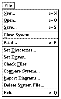
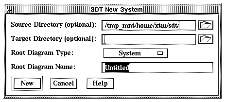
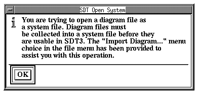
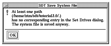
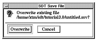
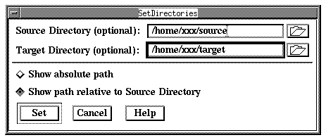
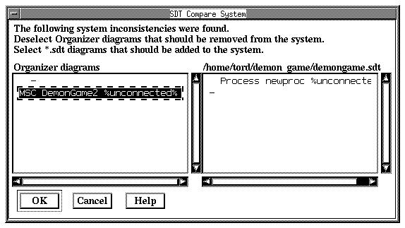
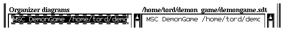
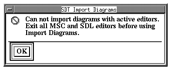
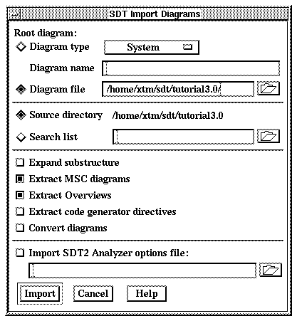
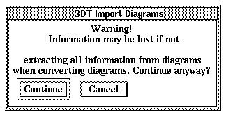
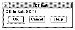
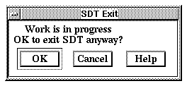
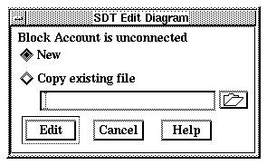
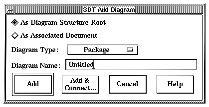
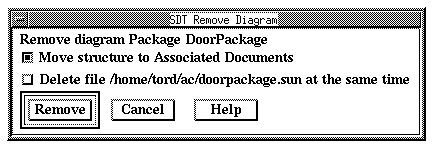
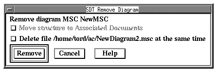
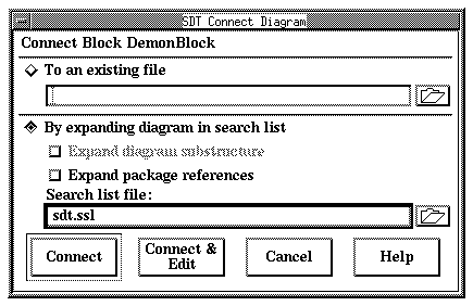
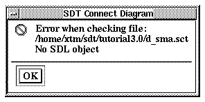
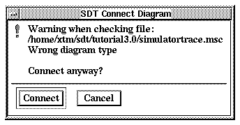
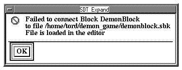
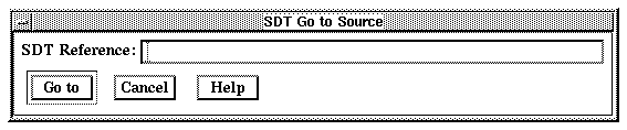
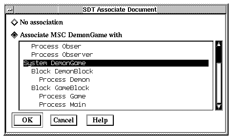
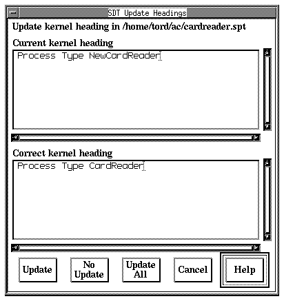
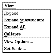
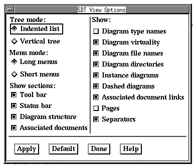
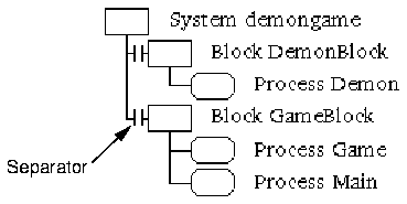
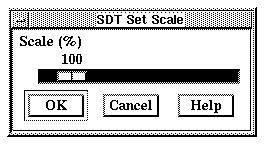
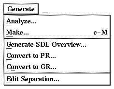
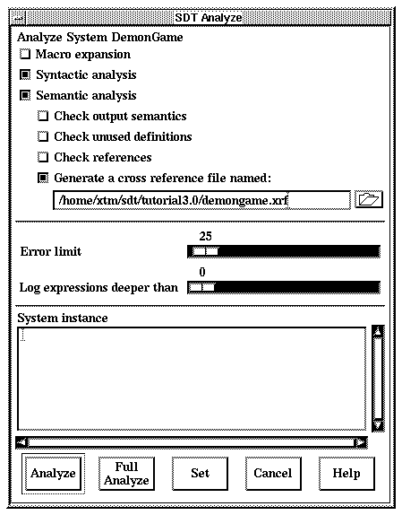
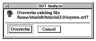
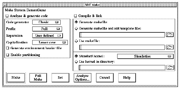
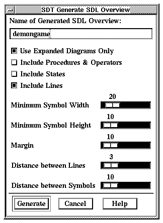
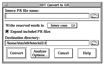
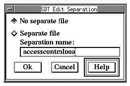
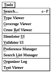
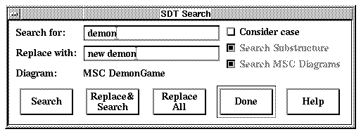
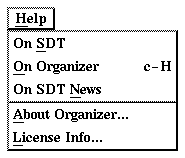
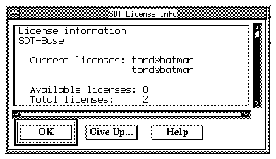
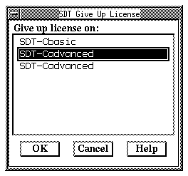