 Table of Contents
  Previous Chapter 4 Printing Information
This chapter describes how you produce printouts of the information that is managed by SDT.
For a reference to the Print Utility user interface and the various printout formats that are supported, see chapter 29, The Print Utility.
Virtually all of the SDT tools that provide a graphical user interface manage information that may be printed. It is possible to print the information that is managed by an individual tool, such as a graphical editor or a viewer, or to print all (or parts of) information that is related to an SDL structure, from the Organizer.
Previous Chapter 4 Printing Information
This chapter describes how you produce printouts of the information that is managed by SDT.
For a reference to the Print Utility user interface and the various printout formats that are supported, see chapter 29, The Print Utility.
Virtually all of the SDT tools that provide a graphical user interface manage information that may be printed. It is possible to print the information that is managed by an individual tool, such as a graphical editor or a viewer, or to print all (or parts of) information that is related to an SDL structure, from the Organizer.
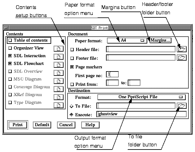
To print information, you operate the Print command from the tool's File menu. SDT responds by issuing the the Print Dialog. The appearance of this dialog differs slightly depending on what tool you are printing from, Figure 142 below shows the Organizer's print dialog.
Figure 142 : The Organizer Print Dialog.
-----
(fig)

-----
You can read more about the dialog's features in chapter 29, The Print Utility.
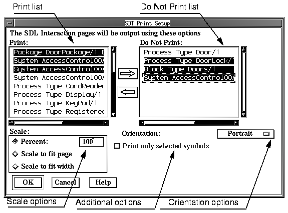
A number of print options are available in the print dialog. Other print setup options are available, when you require access to the Print Setup Dialog.
Figure 143 : The Print Setup Dialog.
-----
(fig)

-----
To include a table of contents into your printout:
- Select the Print command from the Organizer's File menu...
----------------------------------------------------------
(fig)
- Alternatively, click the quick button for Print.
----------------------------------------------------------
- Turn the Table of Contents toggle button on.
- Adjust, if required, other options and click the Print button to order the tool to start printing.
The table of contents is printed first in the printout.
To include an Organizer Structure (i.e. the contents of the Organizer Main Window) into your printout:
- Select the Print command from the Organizer's File menu.
----------------------------------------------------------
(fig)
- Alternatively, click the quick button for Print.
----------------------------------------------------------
- Make sure the Organizer View toggle button is on.
- Adjust, if required, other options and click the Print button to order the printout.
It is possible to print one SDL diagram, one SDL page only or a subtree of SDL diagrams managed by the Organizer. Printing individual SDL symbols only is also supported.
To print one SDL diagram:
- Open the diagram in an SDL Editor.
- From the SDL Editor's File menu, select the Print command.
----------------------------------------------------------
(fig)
- Alternatively, click the quick button for Print.
----------------------------------------------------------
- To make sure all pages will be included in the printout, click the Setup button.

- Press the <SHIFT> key and click the left arrow button, to transfer all pages to the left list (the list titled Print):
- Adjust, if required, other setup options and click the OK button.
- Adjust, if required, other options and click the Print button to order the printout.
An alternative way to print one SDL diagram is to select it and print it from the Organizer. See "Printing Multiple SDL Diagrams", below.
To print multiple SDL diagrams:
- In the Organizer Main Window, select the SDL diagram that will define the root of the subtree to be printed. (SDL diagrams that are included in the subtree will by default be included in the printout).
- Operate the Print menu choice from the File menu.
----------------------------------------------------------
(fig)
- Alternatively, click the quick button for Print.
----------------------------------------------------------
- If SDL interaction diagrams are to be printed, make sure the SDL Interaction toggle button is turned on.
- If some of the interaction diagrams are to be included or excluded from the printout, click the setup button.

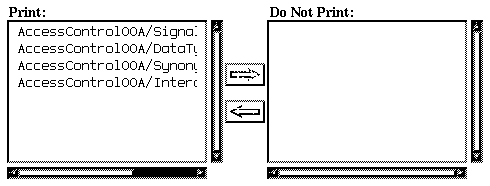
- Transfer the diagrams to be printed or not between the lists (Print / Do Not Print) by selecting them and clicking the left and right arrow buttons. Pressing the <SHIFT> key while clicking the buttons transfers all diagrams from one list to the other:

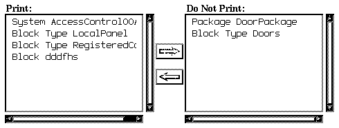
- Adjust, if required, other setup options and click the OK button.
- If SDL flow diagrams are to be printed, make sure the SDL Flowchart toggle button is turned on. Repeat steps 4. and 5. above.
- Adjust, if required, other options and click the Print button to order the printout.
Printing one ore multiple SDL pages must be done from within the SDL Editor:
- Open the diagram in an SDL Editor.
- Select the Print command from the File menu.
----------------------------------------------------------
(fig)
- Alternatively, click the quick button for Print.
----------------------------------------------------------
- Click the Setup button if more than one page is to be printed. By default, only the current SDL page will be included in the printout.

- Click the left and right arrow button to transfer a page between the left list (pages to print) and the right list (pages not to be printed).
- Pressing the <SHIFT> key while clicking transfers all pages from one list to the other.
- Adjust, if required, other setup options and click the OK button.
- Adjust, if required, other options and click the Print button to order the printout.
It is possible to restrict the scope of print to the selected SDL symbols only:
- In the SDL Editor, select the symbols to be printed.
- From the SDL Editor's File menu, select the Print command...
----------------------------------------------------------
(fig)
- Alternatively, click the quick button for Print.
----------------------------------------------------------
- Click the Setup button.

- Turn the Print only selected symbols button on.

- Adjust, if required, other setup options and click the OK button.
- Adjust, if required, other options and click the Print button to order the printout.
SDL Overviews may be printed locally from the SDL Editor (see "Printing one SDL Diagram" on page 258 for how to do this) or may be included in a global printout from the Organizer.
To include SDL Overview diagrams in a print job ordered from the Organizer:
- In the Organizer Main Window, select the SDL diagram that will define the root of the subtree to be printed. (Overview diagrams that are included as links in the subtree will by default be included in the printout). Operate the Print menu choice from the File menu...
----------------------------------------------------------
(fig)
- Alternatively, click the quick button for Print.
----------------------------------------------------------
- You may also select any SDL Overview link before ordering the printout.
- Make sure the SDL Overview diagram toggle button is turned on.
- Click the Setup button.

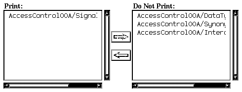
- You may now transfer the SDL Overview diagrams to be printed or not between the two lists (Print / Do Not Print) by selecting them and clicking the left and right arrow buttons.

- Pressing the <SHIFT> key while clicking the buttons transfers all diagrams from one list to the other.
Links to SDL Overview diagrams (i.e. Overview diagrams that are present in the Organizer Diagram Structure) are listed as Overview followed by the name of the diagram. SDL Overview diagrams that are present in the Associated Documents area are listed as Document Overview, followed by the name of the diagram:
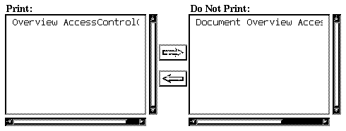
- Overviews are included in the resulting printout at the place they are located in the diagram structure, while Document Overviews are included last in the printout, reflecting their location in the associated documents area.
- Adjust, if required, other setup options and click the OK button.
- Adjust, if required, other options and click the Print button to order the printout.
It is possible to print one or multiple MSCs that are managed by the Organizer.
To print one MSC:
- Open the diagram in an MSC Editor.
- From the MSC Editor's File menu, select the Print command...
----------------------------------------------------------
(fig)
- Alternatively, click the quick button for Print.
----------------------------------------------------------
- Adjust, if required, some options and click the Print button.
An alternative way to print one MSC is to print it from the Organizer. See "Printing Multiple MSCs", below.
To print multiple MSCs:
- In the Organizer Main Window, select the SDL diagram that will define the root of the subtree to be printed. (MSCs that are included as links in the subtree will by default be included in the printout). Operate the Print menu choice from the File menu...
----------------------------------------------------------
(fig)
- Alternatively, click the quick button for Print.
----------------------------------------------------------
- You may also select any MSC before ordering Print.
- Make sure the MSC Diagram toggle button is turned on.
- Click the Setup button.

- You may now transfer the MSCs to be printed or not between the two lists (Print / Do Not Print) by selecting them and clicking the left and right arrow buttons. Pressing the <SHIFT> key while clicking the buttons transfers all MSCs from one list to the other.

Links to MSCs (i.e. MSCs that are present in the Organizer Diagram Structure) are listed as MSC followed by the name of the MSC. MSCs that are present in the Associated Documents area are listed as Document MSC, followed by the name of the MSC:
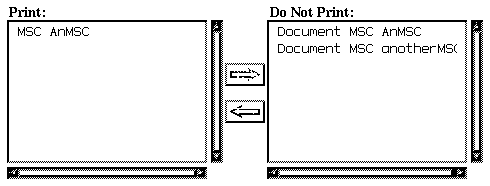
- MSCs are included in the resulting printout at the place they are located in the diagram structure, while Document MSCs are included last in the printout, reflecting their location in the associated documents area.
- Adjust, if required, other setup options and click the OK button.
- Adjust, if required, other options and click the Print button.
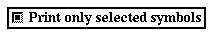
It is possible to restrict the scope of print to the selected MSC symbols only:
- In the MSC Editor, select the symbols to be printed.
- From the MSC Editor's File menu, select the Print command...
----------------------------------------------------------
(fig)
- Alternatively, click the quick button for Print.
----------------------------------------------------------
- Click the Setup button.

- Turn the Print only selected symbols button on.
- Adjust, if required, other setup options and click the OK button.
- Adjust, if required, other options and click the Print button.
You may include an instance ruler into each printed page of an MSC. How to do this when printing from the MSC Editor:
- Open the diagram in an MSC Editor.
- From the MSC Editor's File menu, select the Print command...
----------------------------------------------------------
(fig)
- Alternatively, click the quick button for Print.
----------------------------------------------------------
- Click the Setup button.

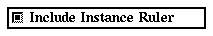
- Make sure the Include Instance Ruler button is turned on.
- Click the OK button.
SDL Type Views may only be printed when the Type Viewer is up and running. They may be printed locally from the Type Viewer or may be included in a global print from the Organizer.
To print a type list:
- Make sure the Type Viewer is up and running.
- Locate the Type Viewer's Main Window. Adjust, if necessary, the window contents with the commands from the View Menu before printing.
- Select the Print command from the Type Viewer's main window...
----------------------------------------------------------
(fig)
- Alternatively, click the quick button for Print.
----------------------------------------------------------
- Adjust, if required, print setup options and other print options.

- Click the Print button to order the printout.
To print a inheritance tree:
- Make sure the Type Viewer is up and running. Adjust, if necessary, the appearance of the inheritance tree with the View Menu commands before printing.
- Select the Print command from the Type Viewer's Tree Window.
----------------------------------------------------------
(fig)
- Alternatively, click the quick button for Print.
----------------------------------------------------------
- Adjust, if required, print setup options and other print options.

- Click the Print button to order the printout.
To include a type list and / or an inheritance tree in a global printout:
- Make sure the Type Viewer is up and running. Adjust, if necessary, the appearance of the type list and the inheritance tree with the various View commands.
- Select the Print command from the Organizer.'s File menu
----------------------------------------------------------
(fig)
- Alternatively, click the quick button for Print.
----------------------------------------------------------
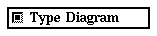
- Make sure the Type Diagram toggle button is turned on.
- If any of the Type Viewer Main Window or Tree Window is to be excluded from the printout, click the Setup button.

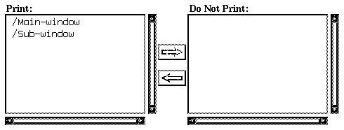
- With the left and right arrow buttons, you can specify what window to print or not to print.

- The type list is identified as /Main-window
- The inheritance tree is identified as /Sub-window.
- Adjust, if required, other setup options and click the OK button.
- Adjust, if required, other options and click the Print button to order the printout.
Cross Reference Diagrams may only be printed when the Cross Reference Viewer is up and running. They may be printed locally from the Cross Reference Viewer or may be included in a global print from the Organizer.
To print a list of definitions of SDL entities from the Cross Reference Viewer:
- Make sure the Cross References Viewer is up and running. Open the file containing the cross-references of your choice.
- Adjust, if necessary, the Main Window contents with the View Menu commands before printing.
- Select the Print command from the File menu in the main window...
----------------------------------------------------------
(fig)
- Alternatively, click the quick button for Print.
----------------------------------------------------------
- Adjust, if required, print setup options and other print options.

- Click the Print button to order the printout.
If the window showing the references to an SDL entity is to be printed, make sure the References Window is active and repeat the steps 2. to 5., above.
To include a Cross Reference Diagram tree in a global printout:
- Make sure the Cross References Viewer is up and running. Open the file with cross-references of your choice.
- Adjust, if necessary, the appearance of the Main Window (showing the list of defined SDL entities) and the References Window (showing the list of references) with the various View Menu commands.
- Select the Print command from the Organizer's File menu...
----------------------------------------------------------
(fig)
- Alternatively, click the quick button for Print.
----------------------------------------------------------
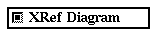
- Make sure the XRef Diagram toggle button is turned on.
- If any of the Cross Reference Viewer windows contents is to be excluded from the printout, click the Setup button.

- With the left and right arrow buttons, you can specify what window to print or not to print.

- The window showing the definitions of SDL entities is identified as /Main-window
- The window showing the references to SDL entities is identified as /Subwindow.

- Adjust, if required, other setup options and click the OK button.
- Adjust, if required, other options and click the Print button to order the printout.
Coverage Diagrams may only be printed when the Coverage Viewer is up and running. They may be printed locally from the Coverage Viewer or may be included in a global print from the Organizer.
To print a coverage diagram from the Coverage Viewer:
- Make sure the Coverage Viewer is up and running. Open the file with coverage results of your choice.
- You may for instance select your preferred view (Transition Coverage view or Symbol Coverage view)
- Adjust, if necessary, the window contents with the View Menu commands before printing.
- Select the Print command from the Coverage Viewer's File menu...
----------------------------------------------------------
(fig)
- Alternatively, click the quick button for Print.
----------------------------------------------------------
- Adjust, if required, print setup options and other print options.

- Click the Print button to order the printout.
If the window showing the coverage details is to be printed, make sure the Coverage Details Window is active and repeat the steps 2. to 6., above.
To include a coverage diagram in a global printout:
- Make sure the Coverage Viewer is up and running. Open a suitable file with coverage results.
- Select the view of your choice (Transition Coverage view or Symbol Coverage view).
- Adjust, if necessary, the appearance of the Main Window and the Coverage Details Window with the various View Menu commands.
- Select the Print command from the Organizer's File menu.
- Make sure the Coverage Diagram toggle button is turned on.
- If any of the Coverage Viewer windows contents is to be excluded from the printout, click the Setup button.

- With the left and right arrow buttons, you can specify what window to print or not to print.

- The window showing the coverage tree is identified as /Mainwindow
- The window showing the coverage details is identified as /Subwindow.

- Adjust, if required, other setup options and click the OK button.
- Adjust, if required, other options and click the Print button to order the printout.
Search List Manager views can only be printed locally from the Search List Manager.
To print the contents of the Search List Manager window:
- Make sure the Search List Manager is up and running. Open the search list file of your choice.
- Adjust, if necessary, the main window contents with the various View Menu commands before printing.
- Select the Print command from the Search List Manager's File menu.
- Adjust, if required, print Setup options and other print options.

- Click the Print button to order the printout.
Preference windows can only be printed locally from the Preference Manager.
To print the contents of the Preference Manager window:
- Make sure the Preference Manager is up and running.
- Adjust, if necessary, the window contents with the various View Menu commands before printing.
- Select the Print command from the Preference Manager's File menu.
----------------------------------------------------------
(fig)
- Alternatively, click the quick button for Print.
----------------------------------------------------------
- Adjust, if required, print Setup options and other print options.

- Click the Print button to order the printout.
With SDT, you may generate any of the following output formats when printing:
- PostScript
- Encapsulated PostScript
- Frame Maker Interchange Format
- Interleaf ASCII Format
The output format is specified in the print dialog that is issued when invoking the Print command.
You would typically generate a PostScript file when the printout is to be a self-contained document, suitable for printing.
To generate PostScript:
- Select the One PostScript File option
If you are to include graphics into a document, you should order SDT to produce encapsulated PostScript.
- Select the One EPS File option.
- You may select the One EPS File Per Page option if multiple pages are to be printed. Also, you must specify a Map File that will contain a translation table showing the correspondence between the input diagrams and the files have been generated.
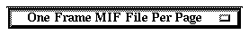
If your computer environment includes FrameMaker, you may take advantage of SDT's ability to generate MIF files.
- Select the One Frame MIF File option.
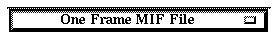
- You may select the One Frame MIF File per page if multiple pages are to be printed. Also, you must specify a Map File that will contain a translation table showing the correspondence between the input diagrams and the files have been generated.
You may also import the printout directly in a FrameMaker document; see "Importing into FrameMaker" on page 280.
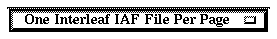
If your computer environment includes Interleaf, you may take advantage of SDT's ability to generate IAF files.
- Select the One Interleaf IAF File option.
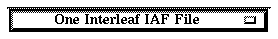
- You may select the One Interleaf IAF File Per Page if multiple pages are to be printed. Also, you must specify a Map File that will contain a translation table showing the correspondence between the input diagrams and the files have been generated.
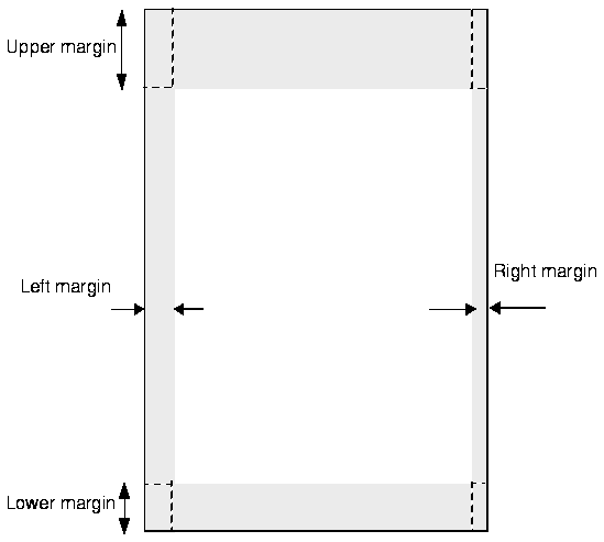
Print margins may be added to the upper, lower, left and right on each printed page.
Figure 144 : Printer Margins.
-----
(fig)

-----
These margins may be defined as preferences using The Preference Manager. See "Print Preferences" on page 1532.
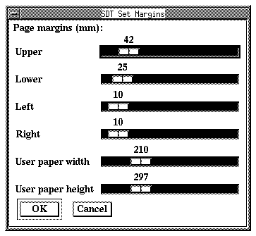
You may also change the margins from within the print dialog. To do this:
- Click the Margins button. The Set Margins dialog is issued:

Figure 145 : Setting the Margins.
-----
(fig)

-----
- Use the slide bars Upper, Lower, Left, Right to adjust the margins to their adequate values.
- Drag to perform coarse adjustments.
- Click left or right on the bar for fine adjustments.
- Click the OK button to apply the new values.
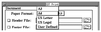
SDT supports a number of predefined paper formats:
- A4, the European standard size (210 * 297 mm)
- A3, the European standard double size (297 * 420 mm)
- US Letter, the American standard (8.5" * 11")
- US Legal (8.5" * 14")
- User Defined, which provides access to a customized size that is set up as a preference using The Preference Manager. See "Print Preferences" on page 1532.
To specify the paper format of your choice:
- Click on the Paper Format option menu and select the appropriate paper size.
You may customize the paper size that will be used during the current print job:
- Click the Margins button. The Set Margins dialog is issued:

Figure 146 : Setting the Margins.
-----
(fig)

-----
- Use the slide bars User paper width and User paper height to adjust the paper size.
- Drag to perform coarse adjustments.
- Click left or right on the bar for fine adjustments.
- Click the OK button to apply the new values.
You may select between landscape and portrait orientations. To change the orientation:
- Click the Setup button.

- Select the orientation of your choice from the Orientation option menu and click OK.
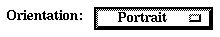
Each category of documents (Organizer View, SDL Interaction diagrams, SDL Flowcharts and so forth) may be printed using different orientations, allowing you for instance to print SDL flow diagrams using portrait orientation while printing SDL Overviews using landscape orientation.
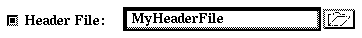
You may specify to include a header and / or footer on each printed page. Headers and footers are defined on textual files of their own, that you create and edit using any text editor available on your computer.
Headers and footers are managed identically. Below you can read about how to add a footer to your printouts.
A header file is created outside SDT with a text editor. In chapter 29, The Print Utility, on page 1467, you can find a description of the exact syntax that each line should follow. Below, an example of a header file and the result it provides when included in an SDT printout is given:
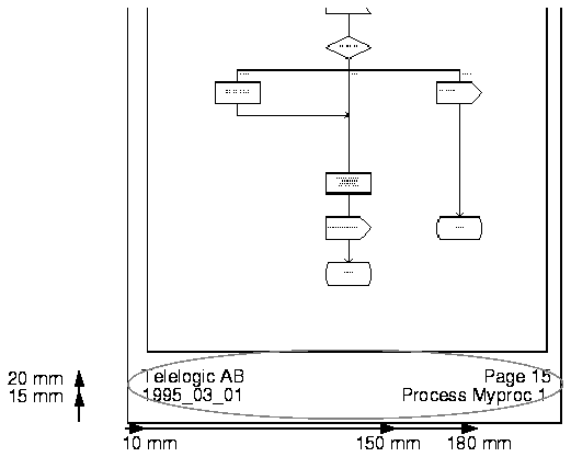
Given that you have a process with the name Myproc, with page 1 printed out on March 1, 1995(1), the 15th printed page would look something like Figure 147.
Example 7 : The Contents of a Footer File.
10 20 Telelogic AB
10 15 <date>
150 15 <diagramtype> <diagramname> <pagename>
180 20 Page <page>
Provides the following result:
Figure 147 : The Resulting Footer.
-----
(fig)

-----
Once you have created a header file, you include it easily by typing the name of the header file into the Header File text field.
Make also sure the Header File toggle button is on.
When printing, SDT allows you to save these results printout on a file of your choice or to order a post-printing processing of the printing results. You may for instance want to send a PostScript printout to a printer or to preview the results in a PostScript previewer before saving the results.
Some examples are given below
- Type in the file name of your choice in the To File text field. Make also sure the To File radio button is turned on.

- Alternatively, you can click the folder button to issue a Standard File Selection Dialog where you specify the file.
- Type in the printer command of your choice in the Execute text field (typically, lpr or any other related command). Make also sure the Execute radio button is turned on.

Type in the previewer command of your choice in the Execute text field (for instance, ghostview). Make also sure the Execute radio button is turned on.

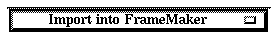
SDT allows you to import a FrameMaker file generated by the Print Utility directly into a FrameMaker document.
- Position the cursor in the FrameMaker document, at the place where to import the file.
- Select the Import into FrameMaker option.
SDT allows you to scale a printout according to the following:
- Using a fixed scaling factor
- Rescaling to fit the page size
- Rescaling to fit the page width.
Each category of documents (Organizer View, SDL Interaction diagrams, SDL Flowcharts and so forth) can be scaled individually, allowing you for instance to scale down SDL Overviews to fit the page size, while scaling MSCs to build a column of pages.
To set the scale option for a category of documents:
- Click the Setup button

- Turn the radio button that corresponds to the option of your choice on
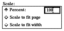
- When specifying a fixed scale, you need to type in the appropriate scaling factor in the Percent text field.
- Close the print setup dialog by clicking the OK button.
- Once the printing scale has been changed and the Print dialog is closed, the Editor updates the location of the page breaks (the dashed horizontal and vertical lines) to match the new printing scale.
- You may want to perform a "dummy" printout to see the impact of the change of printout scale in the Editor before sending the printout to the printer (specify any command such as ghostview in the Execute text field). Repeat the procedure until satisfied and conclude by specifying the correct printer command.
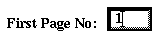
When you order multiple print jobs, you may want to restart the page numbering on each printout with a number different from 1, which is the default value.
To specify the page start numbering:
- Type in the number in the First Page No text field
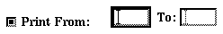
When printing a document that would required multiple pages when printed (depending on its size, the paper format and orientation and the printing scale), you may want to exclude a number of pages from a printout.
To specify the print range:
- Open the document in an Editor (SDL or MSC editor). These tools show the physical page breaks with dashed lines
Figure 148 : Showing the Printer Page Breaks.Figure legend: The picture shows
		thelower right part of physical page 1 of an SDL page. The dashed lines indicate
		wherethe page breaks will be inserted. A page number is inserted at the lower right
		cornerof each page.
-----
(fig)


-----
- Type in the print range in the Print From and Print To text fields. Make sure the toggle button is on.
----------------------------------------------------------------------
Note:
The print range must be in accordance with the page numbering; i.e.
the offset specified in the First Page No should be added.
The page breaks currently visible in the Editor are valid only if the
printing scale is not changed (see step 4. in section "Scaling the
Printout" on page 281).
----------------------------------------------------------------------
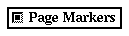
An SDL page or an MSC diagram may require multiple of physical pages when printing it. If you want to print an SDL / MSC document and the document is physically spread over more than one physical page, a feature facilitates the reassembling of the paper sheets into the original page. This feature inserts adjacent page markers on the edge of each physical page. An adjacent page marker looks like a small arrowhead which refers to the adjacent page.
The upper right page has number 1.Physical page numbering follows a "first right, then down" fashion.
Figure 149 : The Page Numbering.
-----
(fig)

-----
To add page markers:
- Turn the Page Markers toggle button on. The page markers will appear on the printout.
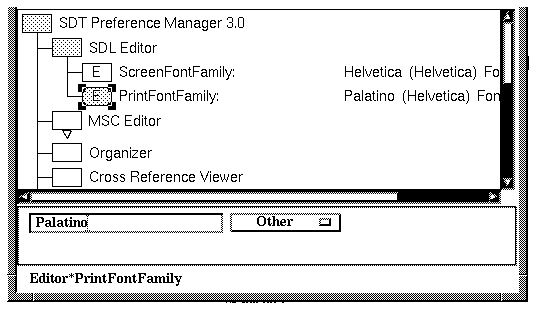
By default only three printer fonts are available for printouts from SDT: Times, Courier and Helvetica. It is possible to add other printer fonts. The requirement is that there exist AFM (Adobe Font Metrics) files for the desired fonts. An AFM file contains the character metrics necessary for correct layout of text in printouts.
- Locate AFM files for the regular, bold, italic and bold italic versions of the font. Many AFM files are available from Adobe Systems Inc. through on-line services (e.g. via ftp from ftp.adobe.com).
- Store the files in the directory $sdtrelease/fontinfo.
- Name the files according to the scheme in the table below. Note that <basename> must be specified using lower case characters (e.g. palatino-I.afm). Otherwise, you are free to choose any <basename> that does not conflict with other fonts or font files.
-----------------------------------------
File contents     File name
-----------------------------------------
regular font      <basename>.afm
bold font         <basename>-B.afm
italic font       <basename>-I.afm
bold italic font  <basename>-BI.afm
-----------------------------------------
- The font may now be chosen as <basename> in the Preference Manager (case is not important in this context):
Figure 150 : Specifying Print Font as Other.Figure legend: Palatino is
		selectedin the current example.
-----
(fig)


-----
- The generated files will use the true name of the font, extracted from the FontName and FamilyName attributes in the AFM files.
This page intentionally left blank
Footnotes
- (1)
- In the current example, the date is printed using ISO format (with underscores as separators).
Table of Contents  Next Chapter