 Table of Contents
  Previous Chapter 29 The Print Utility
This chapter provides a reference to the SDT Print Utility and its user interface, as well as a reference to files used by the Print Utility.
For a guide to how to print from the SDT environment, see chapter 4, Printing Information.
The Print Utility allows to generate printed copies of your SDL diagrams, MSCs and other information managed by SDT, but also to print the requirements to another selected file. Virtually all the information managed by SDT may be printed. A number of options allow to specify what to print, how to print it and where to print it.
Previous Chapter 29 The Print Utility
This chapter provides a reference to the SDT Print Utility and its user interface, as well as a reference to files used by the Print Utility.
For a guide to how to print from the SDT environment, see chapter 4, Printing Information.
The Print Utility allows to generate printed copies of your SDL diagrams, MSCs and other information managed by SDT, but also to print the requirements to another selected file. Virtually all the information managed by SDT may be printed. A number of options allow to specify what to print, how to print it and where to print it.
The Print Utility consists of the following parts:
- The Print Dialog, which is the Print Utility's GUI where the user specifies the options of his choice.
- The Print Generator, where the actual generation of the information to be printed takes place. The user is not involved in this process. The print generator supports two output formats:
- The Print Preferences, that supply the Print Utility with the user's preferred default options.
The Print dialog is issued upon operation of the Print command on the File menu of each SDT tool. Initially, the Print dialog show the user's printing preferences.
The Print dialog has two appearances, depending on what tool the Print command is issued from:
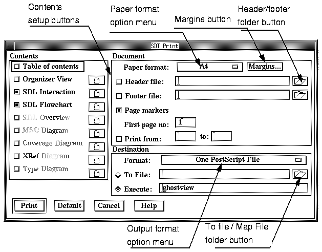
Figure 472 : The Organizer Print Dialog.
-----
(fig)

-----
The dialog consists of the following areas:
If no item is selected in the Organizer, all objects that are managed by the Organizer (i.e. are visible in the Organizer's Diagram Structure Area or Associated Documents Area) will be by default submitted to the print job.
It is however possible to omit some of the SDL diagrams, SDL Overviews and MSCs using the provided setup buttons.
These entities are unknown by the Organizer (meaning that they cannot be included in the structure that is managed by the Organizer). The graphical presentation of these entities is computed as the user requests it by running the Cross Reference Viewer.
Therefore, the graphical presentation of these entities will be included in the printout if the Cross Reference Viewer is running. The resulting printout will reflect the current contents of the tools' windows, i.e. include the contents of the Cross Reference Viewer's Main Window and References Window,
It is possible to restrict the scope of print by excluding the windows not to be printed, using the provided setup buttons.
These entities are unknown by the Organizer (meaning that they cannot be included in the structure that is managed by the Organizer). The graphical presentation of these entities is computed as the user requests it by running the Coverage Viewer.
Therefore, the graphical presentation of these entities will be included in the printout if the Coverage Viewer is running. The resulting printout will reflect the current contents of the tools' windows, i.e. include the contents of the Coverage Viewer's Main Window and Coverage Details Window.
It is possible to restrict the scope of print by excluding the windows not to be printed, using the provided setup buttons.
These entities are unknown by the Organizer (meaning that they cannot
be included in the structure that is managed by the Organizer). Furthermore, this information is computed automatically by the Type Viewer tool. Therefore, the Type Viewer must be running in order to include the information in the resulting printout. The following may be included:
With the setup buttons, it is possible to specify what window to include or exclude from the printout.
The Contents area controls what information to print, through a number of toggle buttons. Each of these toggles identify a groups of documents that may be printed with SDT:
Furthermore, each group of documents that may be printed is supplied with setup buttons, except from the Table of Contents group. Pressing a setup button issues a Print Setup Dialog (see page 1460) where additional options that affect the current group may be set.
This option determines whether a table of contents should be generated or not. The table of contents consists of a textual list with information about what source diagrams and generated diagrams that are included in the printout, with references to physical page numbers.
The table of contents is printed on the first pages that constitute the resulting printout. For each 5:th line in the table of contents, a horizontal
line is inserted, making it easier to associate a given item and its page number.
This option determines whether a printout of the Organizer Main Window should be comprised or not in the generated output. Only the visible parts (i.e. expanded nodes) are included.
The resulting printout will match the Organizer's View Options, i.e. file names, directories etc... will be shown if they are in the Organizer Main window.
This option determines whether the SDL Interaction Diagrams (see page 1160) that are visible in the Organizer Diagram Structure Area and, possibly, in the Associated Documents Area should be included or not in the generated output.
This option determines whether SDL Flow Diagrams (see page 1160) that are visible in the Organizer Diagram Structure Area and Associated Documents Area should be included or not in the generated output.
This option determines whether SDL Overview Diagrams (see page 1160) that are visible in the Organizer Associated Documents Area should be included or not in the generated output.
This option determines whether Message Sequence Charts (see page 1301) that are visible in the Organizer Associated Documents Area should be included or not in the generated output.
This option determines whether Transition Coverage and Symbol Coverage trees (see page 1417 - page 1418) should be included or not in the generated output.
This option determines whether Definitions and Cross References (see page 1394) should be included or not in the generated output.
The resulting output will show the graphical appearance as when displayed in the Cross Reference Viewer with the Filter Entities set to default.
This option determines whether an SDL-92 Type List and SDL Type Inheritance and Redefinition List should be included in the generated output or not.
The resulting output will show the SDL-92 type lists for the SDL system currently in view in the Organizer Diagram Structure Area. The lists will be produced using the options as defined in the Type Viewer's List Options, Tree Options and Symbol Options.
The Document area contains a number of settings that specify the size of the paper to use, the print range, and allow to specify additional information to be printed on each individual page.
The Document options are:
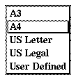
Figure 473 : The Paper Format Popup Menu.
-----
(fig)

-----
The Paper format option menu specifies what paper format the print utility will use. The supported formats are listed by clicking on the option menu (the menu is shown on Figure 473). They are as follows:
- A4, the European standard size (210 * 297 mm)
- A3, the European standard double size (297 * 420 mm)
- US Letter, the American standard (8.5" * 11")
- US Legal (8.5" * 14")
- User Defined, which provides access to a customized size that is set up using the Preferences Tool. The size may also be customized with the Margins button (see page 1449).
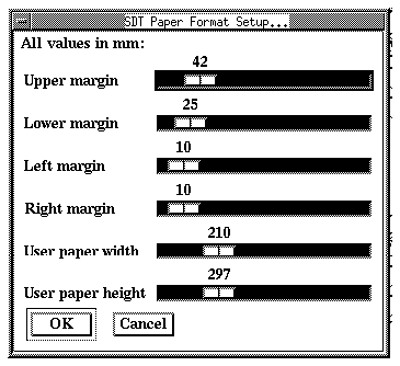
The Margins button provides access to a dialog where the print margins may be specified.
Figure 474 : The Set Margins Dialog.
-----
(fig)

-----
The print margins govern how much space is reserved around the area used when printing (see "Margins" on page 1466). Values are expressed in millimeters.
This feature controls whether or not a header should be printed on each page. The page header is defined on a text file of its own, which needs to be supplied by the user. For information about the contents and syntax of this file, see "Footer and Header Files" on page 1467.
This feature controls the option to include a footer on each printed page.
The functionality is identical to the definition of a header. See "Header File", above.
----------------------------------------------------
Note:
Footer files are not supported in FrameMaker Output.
----------------------------------------------------
This option controls whether adjacent page markers should be inserted at the edge of each physical page.
----------------------------------------------------------------
Note:
Not all diagram types managed by SDT take advantage of the page
marker facility. Header and footer files are not supported in
FrameMaker Output and Interleaf Output.
----------------------------------------------------------------
A diagram may need multiple physical pages when printed (depending on the diagram size and the printing scale). SDT may insert adjacent page markers which facilitate the reassembling of physical paper pages into a diagram. The page marker is a number within an arrowhead, and refers to the adjacent physical page it points to.
- With the toggle button on, page markers will be inserted on each physical page.
- With the toggle button off, no page markers will be inserted. This is the default behavior.
This option assigns a start value for the physical page numbering. Default value is 1.
The intended use is to allow subsequent page numbering for multiple print jobs.
This option controls the page range to be printed. It consists of a toggle button and of two text fields, Print From and Print To.
- If the toggle is off, all physical pages that constitute the printout will be generated.
- If the toggle button is on, the two fields Print From and Print To must be filled with the page range to print.
The Destination area contains print options that affect the output format and the destination of the resulting output.
The options are:
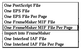
This feature controls what output format will be generated when printing. The format is selected from the output format option menu:
Figure 475 : The Output Format Popup Menu.
-----
(fig)

-----
The supported output formats are:
- One PostScript File
Selecting this option orders SDT to produce one self contained PostScript document.
- One EPS(1) File
If only one page is to be printed, this option is valid and will result in an EPS File containing one physical page. If the Print setup caused more than one physical page to be printed, only the first page will be printed.
- One EPS File Per Page
This format implies that the output will be in the form of multiple EPS files, placed in a specified directory. Along with the EPS files, a map file containing the translation scheme is produced. See "To File / Map File" on page 1454.
- One Frame MIF File(2)
This format signifies the generation of one FrameMaker MIF file. The file will contain a number of contiguous, cropped anchored frames.
- One Frame MIF File Per Page
This option produces one FrameMaker MIF file per page. A map file is also produced, showing the translation table. See "To File / Map File", below.
- Import into Frame Maker
If an instance of Frame Maker is found up and running, this option generates a Frame Maker MIF temporary file that will be imported into an anchored frame, placed below the current insertion point in the active Frame Maker document. If no instance of Frame Maker is found, then SDT attempts to start one with the command imaker and creates a new Frame Maker document, showing the contents of the file.
-------------------------------------------------------------------
Note:
To have this print option function properly, SDT and Frame Maker
must run on the same computer.
Temporary files are stored on the directory designated by the envi
ronment variable TMPDIR. The variable must be set up as a complete
path specification such as setenv TMPDIR /tmp Specifying
TMPDIR such as setenv TMPDIR . is not sufficient.
-------------------------------------------------------------------
See also "Running SDT and Frame" on page 1015 in chapter 20, SDT On-Line Help for how this options functions when multiple instances of FrameMaker are running on your computer.
- One Interleaf IAF File(3)
This format produces one Interleaf ASCII Format file.
- One Interleaf IAF File per Page
This option produces one Interleaf ASCII Format file per page. A map file is also produced, showing the translation table. See "To File / Map File", below
The name of this radio button depends on the specified Format.
- For a format that generates one output file (i.e. the format name ends with Per Page), the toggle is titled To File.
- Otherwise, the toggle will read Map File.
See "Map File" on page 1472 for a description of the map file contents.
When this radio button is on, a file name where the generated output is put must be specified.
With this radio button turned on, a map file must be specified. This map file will contain a translation scheme of all files generated (containing information about SDL diagram / page and the corresponding printout file). The naming algorithm of the generated files will ensure a fixed mapping between a diagram and the generated files between two subsequent Print jobs. However, if the input to the Print utility is changed (it's size!), this is not necessarily true.
See "Map File" on page 1472 for a description of the contents and syntax of a map file.
With this radio button on, SDT will execute an OS command, using the generated output file as input to the OS command. Typically it is to load a printer with a PostScript file. Another example of use is to send the resulting PostScript code to a PostScript previewer.
The default command is specified with the Preferences Tool.
Clicking the Print button orders printing with the current settings. The Print utility first performs a diagnostic and range check on the settings to identify any errors. If any errors are detected the user is prompted to correct the problem.
If all setting are found correct, SDT closes the Print dialog and starts the print job.
Clicking the Revert button reverts all current settings to default settings, picking values from preferences and built-in defaults.
Clicking Cancel stops the current activity and returns control to SDT with no print action having been taken.
This section discusses the scope of print and the available print options when the following commands are issued:
When invoked from another tool than the Organizer, the Print Utility will only print the information that is currently processed (i.e. visible in any of the windows) by the calling tool.
The default scope of print is the active SDL Editor Window, i.e. the SDL page currently being edited. With the setup button, the scope of print may include any of the pages contained in the SDL diagram, or be restricted to the SDL symbols currently selected in the active window.
See also "Print Options" on page 1458.
The default scope of print is the active SDL Editor Window, i.e. the SDL Overview diagram currently being viewed.
See also "Print Options" on page 1458.
The default scope of print is the active MSC Editor Window, i.e. the MSC currently being edited. With the setup button, the scope of print may be restricted to the MSC symbols currently selected in the active window.
See also "Print Options" on page 1458.
The default scope of print are the contents of the Type Viewer's Main Window and Tree Window. With the setup button, it is possible to specify what window to include or exclude from the printout
See also "Print Options" on page 1458.
The scope default scope of print are the contents of the Cross Reference Viewer's Main Window and References Window. With the setup button, it is possible to specify what window to exclude from the printout.
See also "Print Options" on page 1458.
The scope default scope of print are the contents of the Coverage Viewer's Main Window and Coverage Details Window. With the setup button, it is possible to specify what window to exclude from the printout.
See also "Print Options" on page 1458.
The scope of print is the current contents of the Search List Manager's Main Window.
See also "Print Options" on page 1458.
The scope of print is the current contents of the Preferences Manager Window.
See also "Print Options" on page 1458.
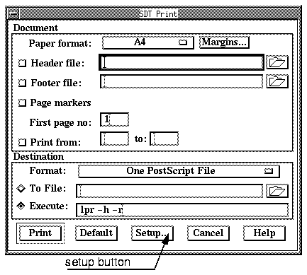
The Print Dialog looks like this when printing from an SDT tool different from the Organizer:
Figure 476 : The Print Dialog from an SDT Tool.Figure legend: The illustration
		showsthe appearance of the dialog when invoking the Print command from a tool
		differentfrom the Organizer.
-----
(fig)


-----
The available options are:
Clicking the Print button orders printing with the current settings. The Print utility first performs a diagnostic and range check on the settings to identify any errors. If any errors are detected the user is prompted to correct the problem.
If all setting are found correct, the SDT tool closes the Print dialog and starts the print job.
Clicking the Revert button reverts all current settings to default settings, picking values from preferences and built-in defaults.
Clicking the Setup button issues a Print Setup Dialog where additional options may be set up. The amount of setup options differs between SDT tools.
Clicking Cancel stops the current activity and returns control to SDT with no print action having been taken.
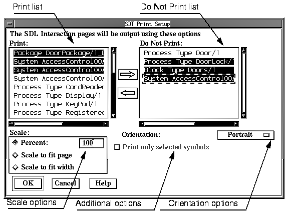
The Print Setup dialog is issued when clicking any of the setup buttons in the Print dialog. It allows to setup a number of options that will affect the current group of documents only (see "Contents" on page 1446 for a list of documents that may be printed).
The Print Setup dialog when issued from the Organizer is illustrated below. The amount of options is reduced when printing from other tools.
Figure 477 : The Print Setup Dialog.
-----
(fig)

-----
The two lists show all documents that are included in the current category of documents. Each item in the list represents a document, identified by its name and possibly a page name.
Clicking a document in either list selects it. A click on a selected item deselects it. Multiple selection is possible.
When printing MSCs, links to MSCs (i.e. MSCs that are present in the Diagram Structure) are listed as MSC followed by the name of the MSC. MSCs that are present in the Associated Documents area are listed as Document MSC, followed by the name of the MSC.
MSCs are included in the resulting printout at the place they are linked in the diagram structure, while Document MSCs are included last in the printout, reflecting their location in the associated documents area.
The same principle as above ("Print / Do Not Print MSCs") is applicable. SDL Overview links are listed as Overview, while SDL Overview in the associated documents area are listed as Document Overview.
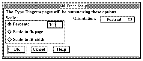
Scale options are provided for each category of documents. The following options are supported:
With the Percent radio button on, the printout of the current document category will be scaled using the value defined in the Percent text field. Default scale is 100%.
With the Scale to fit page radio button on, the printout will be rescaled if needed to fit the physical paper size. The smallest scale is 20%.
With the Scale to fit width button on, the documents will be rescaled in order to fit the physical paper width. The result becomes a column of pages constituting each document. The smallest scale is 20%.
The Orientation options popup menu provides the choice between the following orientations:
The effect of this option is to rotate the resulting printout in order to optimize paper use.
Some Additional options may be available, depending on what category of documents are the subject of being printed:
Figure 478 : The SDL Editor Print Setup Dialog.
-----
(fig)

-----
- Print Only Selected Symbols:
The toggle button controls whether the printout should comprise the objects currently selected in the SDL Editor or the SDL page in its whole. This option is disabled if no object is selected or if more than one SDL Editor window has a selection.
- Print / Do not Print: The left list contains the current SDL page. This SDL page will be printed by default. The right list contains the remaining pages that are included in the SDL diagram.
- Scale: See page 1461 for description.
- Orientation: See page 1462 for description.
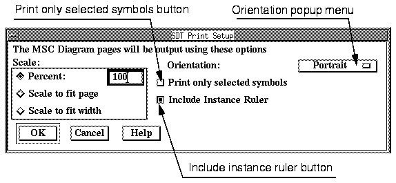
Figure 479 : The MSC Editor Print Setup Dialog.
-----
(fig)

-----
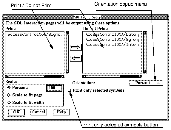
The remaining SDT tools Print Setup dialog all look like Figure 481 (except from the leading text that differs from tool to tool)
Figure 481 : The Type Viewer Print Setup Dialog.Figure legend: The picture
		showsthe Type Viewer's Print Setup dialog.
-----
(fig)


-----
- Scale options: See page 1461 for description.
- Orientation option: See page 1462 for description.
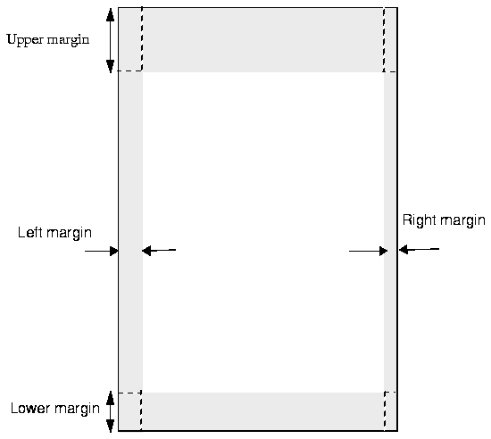
The margins that are inserted to the left, right, on top and bottom of a printout are defined as preference parameters (see "Print Preferences" on page 1532).
Margins are calculated with respect to the closest border and remain unaffected when rescaling, changing the paper size or the orientation of the printout.
Figure 482 : The Printing Margins.
-----
(fig)

-----
This section provides a reference to the syntax to use when creating a file with header or footer definitions.
The header and footer files give the user control of the layout and information to appear in the header and footer respectively. The format is ASCII based and line oriented. A number of variables are available, providing additional information of the kind of diagram printed.
Text is written on a white background, which becomes visible if the text appears on top of any graphical object.
The priority order for writing headers and footers is as the inverse order in which the items appear in the file. That is any text, variable or graphical symbol, overwrites an already written item. (The last row in the file has the highest priority).
The syntax used in the header and footer files is given below in a BNF notation:
File     ::= ( <LINE> | <EXTENSION-LINES> | <EPSF> ) *
<LINE>    ::= <X> <Y> ( <TEXT> | <VARIABLE> ) + \n
<X>     ::= integer, x - position in millimeter
<Y>     ::= integer, y - position in millimeter
<TEXT>     ::= any ASCII text - no newlines allowed
<VARIABLE> ::= any variable as described  on page
1468,
<EXTENSION-LINES> ::= any of the extensions as
defined on page 1469.
<EPSF>    ::= EPSF <X> <Y> <FILE>
<FILE>    ::= user provided filename containing EPS code

-------------------------------------------------------------------
Note:
The positions are relative the upper left corner of the physical pa
per in the header and the lower left corner in the footer.
-------------------------------------------------------------------
The following variables are supported in header and footer files:
------------------------------------------------------------------------
Variable Explanation
------------------------------------------------------------------------
<date> As set by the Print preference date.
<diagramname> The name of the diagram. Ignored if the printed
diagram was not one of:
� SDL diagram
� SDL Overview diagram
� MSC.
<diagramtype> The type of the diagram. Ignored if the printed
diagram was not one of:
� SDL diagram
� SDL Overview diagram
� MSC.
<pagename> The logical name of current page. Ignored if the
printed diagram was not one of:
� SDL diagram
� SDL Overview diagram.
<file> The current file being printed. Ignored if no cor
responding file exists. It could be a New
(unsaved) file being printed or it could be a Type
View which has no corresponding file.
<page> The current page number.
<directory> The directory where the current file is located.
Ignored if no corresponding file exists. It could
be a New (unsaved) file being printed or it could
be a Type View which has no corresponding file.
------------------------------------------------------------------------
(i.e. variables used in SDT 2.3)
--------------------------------------------------------------
Variable      Explanation
--------------------------------------------------------------
<area>  Prints Work Area or Original Area in plain text
              depending on if the diagram was found in the
              source directory or not.
              The variable is available for backwards compati
              bility only.
--------------------------------------------------------------
Below are listed the extensions that enhance the appearance of the header and footer.
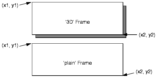
The keyword FRAME makes a frame appear at any position on the paper. The function is intended for framing the header and/or footer.
The exact format is:
FRAME x1 y1 x2 y2 [type]
where the start and stop positions are given in millimeters. The optional type argument may be either 3D or plain (default).
Figure 483 : 3D Frame and Plain Frame.
-----
(fig)

-----
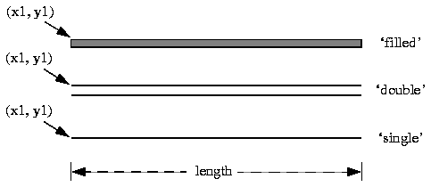
A separator is a horizontal line which is intended to separate the header and/or footer from the data area of a printed page.
The SEPARATOR statement has the general format:
SEPARATOR x1 y1 length [type]
where the start position and length of the separator are given in millimeters. The optional type argument may be either
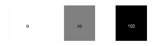
The BOX keyword may be used to make a filled rectangle appear anywhere on the paper. It is intended for highlighting sections of the header and/or footer.
The format is:
BOX x1 y1 x2 y2 [grayscale]
where the start and stop positions are given in millimeters. The optional grayscale argument is a number in the range 0 to 100, where 100 means black and 0 means white. The default is 50.
Figure 485 : Boxes.Figure legend: The picture shows three boxes, one white box
		(grayscale= 0), one medium-gray (50) and one black box (100).
-----
(fig)


-----
When multiple output files are generated for one input diagram, a map file is also generated, showing the translation table between input diagrams and resulting files. The name of this file should be specified in the text field To file / Map File.
The map file is an ASCII text file containing lines of the format:
<filename> "[<diagram type>]" "[<diagram name>]"
"[<page name>]"
where <filename> is an absolute path to a generated file. The file name is composed of:
- The first four letters of the diagram name (fewer if the diagram name is shorter than four letters)
- The first two letters of the page name
- An extension.
If this naming scheme generates two files with the same name, a number (1-99) is added to the second file name, preceding the extension.
Example 33 : Contents of a Map File
...
/usr/steve/SDT/doc/ContDe.eps "Block" "Controller"
"Declarations"
...
/usr/steve/SDT/doc/ContDe1.eps "Block" "Container"
"Declarations"
...
Should either of the descriptive <diagram type>, <diagram name> or <page name> fields be inapplicable to an item, the corresponding field in the map file will be empty (i.e. "").
This section is a reference to the output generated by SDT's print utility.
PostScript output may be generated as one standard PostScript file or one or more Encapsulated PostScript (EPS) files. When multiple EPS files are generated, a translation table will also be produced in a Map File, linking the name of a generated file to the contents.
A normal print operation generate one PostScript document. All data is represented uniformly, using the same paper format, header, footer etc. Only the scale and orientation might vary between pages.
The EPS output makes use of the scale and orientation settings for each document category. Since EPS files are not clipped, the internal scale has little importance when the file is imported into an external documentation or desktop publishing system.
Header, footer and adjacent page markers are not included in the output.
The scaling options are handled as follows:
- Scale to Fit Page - Each logical page is output as one EPS file with an internal scale adjusted to fit the entire logical page into the bounding box given by the current paper format and margins. When the EPS files are scaled into external documentation software, this will correspond to the "Fit Into Page" option for PostScript files.
- Percent- As Scale to Fit Page, but with a user defined internal scale.
- Scale to Fit Width - As Scale to Fit Page, but with the internal scale adjusted to fit the width of the logical page into the space given by the paper width and the left and right margins.
Expanded texts are the text contained in such symbols that are minimized(4) in a graphical page, see "Text / Additional Heading / Package Reference Symbols" on page 1175.
Expanded text is output as plain text using the font specified by the SDT*PrintFontFamily and SDT*PrintTextHeight preferences.
Expanded text in EPS output is stored on separate files. One text file is generated for each logical page containing expanded text, regardless of the number of expanded texts in that logical page.
- When generating multiple EPS files, the text file for a logical page called <x>.eps will be <x>.exp.
- When printing to one EPS file, the text file for <x> will be <x>.exp.
The generated PostScript code conforms to either of these standards:
- PostScript Language Document Structuring Conventions - Version 3.0
- Encapsulated PostScript File Format - Version 3.0.
FrameMaker output may be generated either as:
- one MIF(5) file containing cropped anchored frames
or
- one or more MIF files containing one logical page each.
The generated pages are the same in both cases. A translation table is also generated in the latter case.
Depending on the scale setting (see "Scaling in EPS Files" on page 1473), each logical page will be represented as one or more cropped anchored frames in the output.
Header, footer and adjacent page markers are not included in the output.
Expanded text is inserted as plain text after the anchored frames generated for the corresponding logical page. In order to preserve the appearance of the users original text, hard returns are inserted where newlines are found.
The generated MIF files conform to Frame Maker Interchange Format version 4.00.
Interleaf output may be produced as:
- one IAF(7) file containing anchored frames
or
- one or more IAF files containing one logical page each.
The generated pages are the same in both cases. A translation table is also generated in the latter case.
Depending on the scale setting (see "Scaling in EPS Files" on page 1473), each logical page will be represented as one or more anchored frames in the output.
Header, footer and adjacent page markers are not included in the output.
Expanded text is inserted as plain text after the frames generated for the corresponding logical page. In order to preserve the appearance of the users original text, hard returns are inserted where newlines are found.
The generated IAF files conform to Interleaf ASCII Format version 8.0 (used in Interleaf 5).
Footnotes
- (1)
- EPS stands for Encapsulated PostScript
- (2)
- MIF stands for Maker Interchange Format.
- (3)
- IAF stands for Interleaf ASCII Format.
- (4)
- Meaning resized to a minimal size.
- (5)
- MIF stands for Maker Interchange Format.
- (6)
- See "Handling of Expanded Text in PS" on page 1474 for info about expanded text.
- (7)
- IAF stands for Interleaf ASCII Format.
- (8)
- See "Handling of Expanded Text in PS" on page 1474 for info about expanded text.
Table of Contents  Next Chapter

