 Table of Contents
  Previous Chapter 25 The MSC Editor
This section is a reference to the rules that govern how a simulation may be traced by generating a Message Sequence Chart.
Previous Chapter 25 The MSC Editor
This section is a reference to the rules that govern how a simulation may be traced by generating a Message Sequence Chart.
The Message Sequence Chart Editor may be used as a graphical trace tool, which features the automatic generation of a Message Sequence Chart from a simulation.
- The results of the simulation may be presented on line in an MSC Editor window, in which each event of interest will be appended to the chart in order to build up an MSC which reflects the history of the simulation.
- It is also possible to run the simulation, save the results on a simulator MSC log file and open the file from the MSC (see "Open" on page 1312).
- The commands that start up the logging of MSC events, set up the scope of trace, stop the logging of events, and so on, are given to the simulator monitor. See chapter 7, Simulating a System in the User's Guide.
First, the scope of trace should, if necessary, be set to the unit which is currently of interest. This is done with the command SetMSCTrace.
The graphical trace is then started with a dedicated command from the simulator monitor. See StartInteractiveMSCLog in chapter 32, The Simulator. In response to this command, the following happens:
- In the Organizer, a reference to a Message Sequence Chart is added to the Associated Documents Area. The diagram is assigned an unique name.
- An instance of the Message Sequence Chart Editor window is activated on the newly created MSC.
- The current status for the simulation is presented by displaying all SDL process instances that exist at the time when ordering the command StartInteractiveMSCLog.
The mapping rules which govern how SDL events are transformed into MSC symbols are summarized in the following table:
------------------------------------------------
SDL Event                MSC Symbol
------------------------------------------------
Signal                   Message
·  Output                ·  Sending
·  Input                 ·  Consumption
Signal to self           Message to self
·  Output                ·  Sending
·  Input                 ·  Consumption
Timer                    Timer
·  Set                   ·  Set
·  Reset                 ·  Reset
·  Implicit reset        ·  Implicit reset(a)
·  Input                 ·  Timeout
Create of process        Create
--                       Instance end
Stop of process          Stop
Environment              Environment instance(b)
System

                 Instance


<system name>      <instance kind>
Substructure

           Instance


<system name>      <instance kind>
Block

                  Instance


<block name>       <instance kind>
Process

                Instance


<process name>

    <instance kind>


<instance number>  <instance name>
------------------------------------------------
- (a)
- See note on page 1364.
- (b)
- The system's environment is denoted by 1:env
When running the simulation, each SDL event of interest (in the scope of MSC Trace) that takes place will cause the corresponding MSC symbol to be drawn in the drawing area of the MSC Editor.
Default layouting algorithms are use. Each event causes the insertion point to be incremented downwards with one vertical spacing unit, keeping the intuitive feeling of absolute order between events. An event could be, for instance, the output or the input of an SDL signal. However, if an output event is immediately followed by an input event, no incrementation will take place.
Once an SDL signal is output, it is immediately placed into the input port of the receiving process instance. There may, however, be other pending SDL signals in this queue, which means that the signal might not be processed immediately. Therefore, when a signal is output, it is illustrated as received by drawing a horizontal line, marked at its end with an asterisk. See the first message in Figure 383 on page 1325.
When an SDL signal is input, the vertical position for the next event may have moved down in comparison to the position of the signal output. An input of a signal is illustrated by redrawing the line representing the message with its end point connected to the new vertical position. (If an output event is immediately followed by an input, there is no change in vertical position.) The asterisk is removed. See the third message in Figure 383 on page 1325.
-------------------------------------------------------------------
Note:
In the case messages remain "asterisk-marked" for a "long" time,
this may be interpreted as some kind of erroneous behavior which
requires special attention. Messages that are never consumed indi
cate that some design error might have been introduced in the SDL
system. It is up to the user to decide whether the time which has
elapsed since a message was sent should be considered as exceeding
a reasonable value. See the second message in Figure 383 on page
1325.
-------------------------------------------------------------------
Each time an SDL process is dynamically created, a process create will be drawn from the source instance axis, and the created instance will be positioned according to the insert and grouping modes that is set (see "Insert Options" on page 1334). This guarantees that no overlapping instance axes will take place.
- If an instance is stopped (by an instance end symbol), the space which becomes available beneath the instance end symbol will not be reused for new instance axes.
- The Message Sequence Chart Editor will automatically enlarge the MSC size when the MSC has grown so that it reaches the bottom or right of the drawing area. The drawing area is enlarged according to the value of a preference parameter.
The Message Sequence Chart Editor may handle four different timer statuses resulting from a simulation:
- Set
- Reset
- Implicit Reset
- Consumed.
See Figure 384 on page 1326.
----------------------------------------------------------------------------
Note:
The implicit reset timer status is a non-ITU addition to the MSC Ed
itor. An implicitly reset timer is immediately set again to its original
value after it is reset. It is illustrated in the same way as a reset timer.
----------------------------------------------------------------------------
All interchange of information between the SDL system and its environment is displayed by sending / receiving messages to or from an instance with the name 1:env. This instance is placed at the leftmost position on the drawing area.
Graphically, in the Message Chart Editor, the concept conditional trace (see "Scope of Trace for Generation of Message Sequence Charts" on page 1831 in chapter 32, The Simulator) is illustrated as sending or receiving messages to / from an instance with the name Void. The purpose of the Void instance is to document that a message exchange actually took place without focusing on the sending / receiving instance.
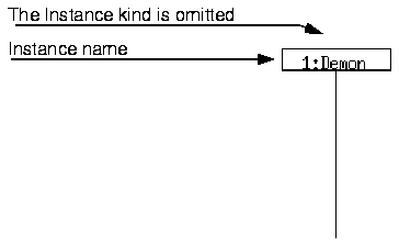
The ITU recommendation Z.120 allows several ways of using the two text fields Instance name and Instance kind (see page 1308)
When generating a Message Sequence Chart, the SDL Process Name and Instance Name are concatenated to build up one (MSC) Instance Kind. The order is however reversed in order to comply with the Z.120 definition.
Example 31 : Instance Name and Instance Kind
Assume the simulation program contains an instance of the SDL process with the name = Demon and instance number = 1 This would be displayed as the following instance:
Figure 411 : The Use of the Instance Text Fields in a Simulation
-----
(fig)

-----
Having terminated the trace (either by stopping the simulation or turning the MSC trace off), the user is responsible for saving the Message Sequence Chart(s) that are the results of the simulation.
This page intentionally left blank
Table of Contents  Next Chapter